


Engineerblogger
March 6, 2012
The use of ground robots in military explosive-ordinance-disposal missions already saves many lives and prevents thousands of other casualties. If the current limitations on mobility and manipulation capabilities of robots can be overcome, robots could much more effectively assist warfighters across a greater range of missions. DARPA’s Maximum Mobility and Manipulation (M3) program seeks to create and demonstrate significant scientific and engineering advances in robot mobility and manipulation capabilities.
The M3 program pursues four parallel tracks of research and development: tool design, improvement of production methods and processes, improvement in control of robot mobility and manipulation, and prototype demonstration.
This video shows a demonstration of the “Cheetah” robot galloping at speeds of up to 18 miles per hour (mph), setting a new land speed record for legged robots. The previous record was 13.1 mph, set in 1989.
The robot’s movements are patterned after those of fast-running animals in nature. The robot increases its stride and running speed by flexing and un-flexing its back on each step, much as an actual cheetah does.
The current version of the Cheetah robot runs on a laboratory treadmill where it is powered by an off-board hydraulic pump, and uses a boom-like device to keep it running in the center of the treadmill. Testing of a free-running prototype is planned for later this year.
While the M3 program conducts basic research and is not focused on specific military missions, the technology it aims to develop could have a wide range of potential military applications.
The DARPA M3 performer for Cheetah is Boston Dynamics of Waltham, Mass.
Source: DARPA
Showing posts with label Design. Show all posts
Showing posts with label Design. Show all posts
Tuesday, March 6, 2012

Thursday, March 1, 2012
High-Performance Innovation:
Engineerblogger
March 1, 2012
As researchers scramble to deliver R&D results and bring products to market, they are turning to high-performance computing. Vendors are competing for their business. Can everyone adapt to the cloud?
What laboratory tool has made the most difference in research and development? Arguably, it’s the personal computer. In the early days of computing, specialized clusters of high-performing processors were often needed for data-intensive tasks. But as chipmakers upheld Moore’s Law, desktop machines and even laptops became powerful enough to handle complex design and processing tasks.
Personal computers are ubiquitous and indispensible, but often are no longer powerful enough, even for daily research tasks such a processing a Microsoft Excel spreadsheet. Circumstances have conspired to force researchers to seek a better solution. As microprocessor speed has stalled, data volume has exploded. In 2004, according to Dave Turek, vice president of deep computing at IBM Corp., Armonk, N.Y., computer scientists recognized the limits of microprocessor technology and realized the best avenue for more performance was to group large numbers of processors together and leverage strength in numbers. Multi-core was born.
Now, through a combination of multicore processing, commoditization of high-end service components, and high-speed communications, high-performance computing (HPC) is handling the heavy lifting of high-technology R&D.
“What really has changed is the migration of traditional techniques and approaches into a non-classical domain. When you peel back the covers, at its core, software is sophisticated mathematics used to answer problems,” says Turek. HPC represents this new domain, where linear programming gives way to counter-intuitive parallel processing and where researchers stand to make tremendous gains in knowledge, if they know how to get the most out it. As a result, research organizations cannot consider adopting HPC without gaining knowledge of the associated software, tools, components, storage, and services that together form the infrastructure for intensive computation.
To read more click here...
March 1, 2012
 |
| ANSYS-CFX was used in the cloud via Windows HPC Server to depict wave formulation around a seafaring vessel. ANSYS is one of many vendors to develop software specifically designed to remotely take advantage of highly parallel computing systems, offering customers high-end performance and faster results. Image: ANSYS |
As researchers scramble to deliver R&D results and bring products to market, they are turning to high-performance computing. Vendors are competing for their business. Can everyone adapt to the cloud?
What laboratory tool has made the most difference in research and development? Arguably, it’s the personal computer. In the early days of computing, specialized clusters of high-performing processors were often needed for data-intensive tasks. But as chipmakers upheld Moore’s Law, desktop machines and even laptops became powerful enough to handle complex design and processing tasks.
Personal computers are ubiquitous and indispensible, but often are no longer powerful enough, even for daily research tasks such a processing a Microsoft Excel spreadsheet. Circumstances have conspired to force researchers to seek a better solution. As microprocessor speed has stalled, data volume has exploded. In 2004, according to Dave Turek, vice president of deep computing at IBM Corp., Armonk, N.Y., computer scientists recognized the limits of microprocessor technology and realized the best avenue for more performance was to group large numbers of processors together and leverage strength in numbers. Multi-core was born.
Now, through a combination of multicore processing, commoditization of high-end service components, and high-speed communications, high-performance computing (HPC) is handling the heavy lifting of high-technology R&D.
“What really has changed is the migration of traditional techniques and approaches into a non-classical domain. When you peel back the covers, at its core, software is sophisticated mathematics used to answer problems,” says Turek. HPC represents this new domain, where linear programming gives way to counter-intuitive parallel processing and where researchers stand to make tremendous gains in knowledge, if they know how to get the most out it. As a result, research organizations cannot consider adopting HPC without gaining knowledge of the associated software, tools, components, storage, and services that together form the infrastructure for intensive computation.
To read more click here...
Wednesday, February 29, 2012
Total Immersion: Immersive Engineering equals Improved Ergonomics
Engineerblogger
Feb 29, 2012
A large and growing part of safety engineering in factories—a.k.a. human factors—is a sharp focus on ergonomics and what it can tell engineers about injuries. The emphasis is on eliminating over-exertion and awkward work postures in repetitive factory jobs.
The solution is immersive engineering, which integrates virtual reality (VR), digital video and related 3-D technologies, computer-aided design (CAD), simulation and analysis, and solid modeling. These theater-like systems surround problem solvers with real-time engineering data presented digitally in life-sized displays with ergonomically accurate, motion-tracked avatars—digital humans.
Computerization and Ergonomics
These efforts mark a new safety push that comes on top of avoiding workplace accidents, especially around machinery, and preventing illnesses due to chemical exposure and excess noise. This new focus within factory safety is a direct extension of longstanding efforts to eliminate repetitive stress injuries such as lower back pain and carpal tunnel syndrome related to computerized office tasks. After four decades of office automation, nearly every office job has been computerized.
Computerization has revolutionized factory work, too, along with myriad mechanical assistance devices, from simple counter-balanced lifters to programmable industrial robots in foundries, welding and painting. Hundreds of thousands of formerly onerous jobs have been made easier, even though so many jobs have been outsourced to low-labor-cost countries.
Much of the reason for the early initial ergonomic success of immersive
engineering relates to a unique strength of the technology. It lets ergonomists and other safety experts solve workplace problems working in the virtual world of the computer. Immersive engineering lets ergonomists work directly with engineers (mechanical, industrial, and manufacturing), productivity managers, and even cost-control staff.
Reaping the Benefits
The results are dramatic, as shown by data from vehicle assembly operations of Ford Motor Co. in Dearborn, Mich. Ford has documented simultaneous reductions in injuries, fewer claims for compensation, shorter learning curves (getting new vehicles into production), lower cost for tooling changes, reduced production costs in general, and higher workplace productivity. The United Auto Workers and other unions support these efforts.
Ford's premiums for worker's compensation insurance have fell by about 55% since 2000, to under $15 million for 2007 from an average of $40 million in the early 1990s. By far the biggest portion of the drop was in repetitive-stress injuries that ergonomic analyses play such a big role in preventing. This is backed up by company medical records that show dramatic reductions in injuries related to spinal compression, back and upper body strains, and shoulder/rotator cuff injuries.
At the same time, new-vehicle quality has soared five times more than the industry average. Ford now matches Honda and they exceed all other manufacturers. Product development times have shrunk eight to 14 months during the past five years. Cost details have not been released but across the industry such costs fall in line with product development time. In just one year, 2007, Ford new-vehicle quality soared an unprecedented 11%, measured three months after sale. The North American industry average was just 2%. In 2009, Ford added an immersive engineering system to its European operations.
A similar system was installed late in 2010 at the Lockheed Martin Space Systems Co. in Denver, Colo., to generate gains in the final assembly of satellites. That is Lockheed Martin's third immersive engineering system.
Key elements of these systems include Jack (Tecnomatix) and Delmia ergonomic and analysis software. The developers (respectively) are Siemens PLM in Ann Arbor, Mich., and Dassault Systemes in Auburn Hills, Mich. The leading developer of motion tracking and analysis systems is Motion Analysis Corp. in Santa Rosa, Calif. The leading systems integrator for immersive engineering is Mechdyne Corp. in Marshalltown, Iowa.
Source: ASME
Feb 29, 2012
 |
| Technicians at Lockheed Martin wear motion tracking sensors (above) as they mime aircraft carrier deck tasks. The information captured animates digital avatars (below) in simulations. |
A large and growing part of safety engineering in factories—a.k.a. human factors—is a sharp focus on ergonomics and what it can tell engineers about injuries. The emphasis is on eliminating over-exertion and awkward work postures in repetitive factory jobs.
The solution is immersive engineering, which integrates virtual reality (VR), digital video and related 3-D technologies, computer-aided design (CAD), simulation and analysis, and solid modeling. These theater-like systems surround problem solvers with real-time engineering data presented digitally in life-sized displays with ergonomically accurate, motion-tracked avatars—digital humans.
Computerization and Ergonomics
These efforts mark a new safety push that comes on top of avoiding workplace accidents, especially around machinery, and preventing illnesses due to chemical exposure and excess noise. This new focus within factory safety is a direct extension of longstanding efforts to eliminate repetitive stress injuries such as lower back pain and carpal tunnel syndrome related to computerized office tasks. After four decades of office automation, nearly every office job has been computerized.
Computerization has revolutionized factory work, too, along with myriad mechanical assistance devices, from simple counter-balanced lifters to programmable industrial robots in foundries, welding and painting. Hundreds of thousands of formerly onerous jobs have been made easier, even though so many jobs have been outsourced to low-labor-cost countries.
Much of the reason for the early initial ergonomic success of immersive
engineering relates to a unique strength of the technology. It lets ergonomists and other safety experts solve workplace problems working in the virtual world of the computer. Immersive engineering lets ergonomists work directly with engineers (mechanical, industrial, and manufacturing), productivity managers, and even cost-control staff.
 |
| Information captured by the Lockheed Martin technicians animates digital avatars in simulations. |
Reaping the Benefits
The results are dramatic, as shown by data from vehicle assembly operations of Ford Motor Co. in Dearborn, Mich. Ford has documented simultaneous reductions in injuries, fewer claims for compensation, shorter learning curves (getting new vehicles into production), lower cost for tooling changes, reduced production costs in general, and higher workplace productivity. The United Auto Workers and other unions support these efforts.
Ford's premiums for worker's compensation insurance have fell by about 55% since 2000, to under $15 million for 2007 from an average of $40 million in the early 1990s. By far the biggest portion of the drop was in repetitive-stress injuries that ergonomic analyses play such a big role in preventing. This is backed up by company medical records that show dramatic reductions in injuries related to spinal compression, back and upper body strains, and shoulder/rotator cuff injuries.
 |
| Allison Stephens directs a study of the physical exertion of an assembly task—installing a console between a vehicle's two front seats—at Ford's Dearborn Ergonomics Laboratory in Michigan. |
At the same time, new-vehicle quality has soared five times more than the industry average. Ford now matches Honda and they exceed all other manufacturers. Product development times have shrunk eight to 14 months during the past five years. Cost details have not been released but across the industry such costs fall in line with product development time. In just one year, 2007, Ford new-vehicle quality soared an unprecedented 11%, measured three months after sale. The North American industry average was just 2%. In 2009, Ford added an immersive engineering system to its European operations.
A similar system was installed late in 2010 at the Lockheed Martin Space Systems Co. in Denver, Colo., to generate gains in the final assembly of satellites. That is Lockheed Martin's third immersive engineering system.
Key elements of these systems include Jack (Tecnomatix) and Delmia ergonomic and analysis software. The developers (respectively) are Siemens PLM in Ann Arbor, Mich., and Dassault Systemes in Auburn Hills, Mich. The leading developer of motion tracking and analysis systems is Motion Analysis Corp. in Santa Rosa, Calif. The leading systems integrator for immersive engineering is Mechdyne Corp. in Marshalltown, Iowa.
Source: ASME
Tuesday, February 28, 2012
Experimental smart outlet brings flexibility, resiliency to grid architecture
Engineerblogger
Feb 28, 2012
Sandia National Laboratories has developed an experimental “smart outlet” that autonomously measures, monitors and controls electrical loads with no connection to a centralized computer or system. The goal of the smart outlet and similar innovations is to make the power grid more distributed and intelligent, capable of reconfiguring itself as conditions change.
Decentralizing power generation and controls would allow the grid to evolve into a more collaborative and responsive collection of microgrids, which could function individually as an island or collectively as part of a hierarchy or other organized system.
“A more distributed architecture can also be more reliable because it reduces the possibility of a single-point failure. Problems with parts of the system can be routed around or dropped on and off the larger grid system as the need arises,” said smart outlet co-inventor Anthony Lentine.
Such flexibility could make more use of variable output energy resources such as wind and solar because devices such as the smart outlet can vary their load demand to compensate for variations in energy production.
“This new distributed, sensor-aware, intelligent control architecture, of which the smart outlet is a key component, could also identify malicious control actions and prevent their propagation throughout the grid, enhancing the grid’s cyber security profile,” Lentine said.
Anatomy of a smart outlet
The outlet includes four receptacles, each with voltage/current sensing; actuation (switching); a computer for implementing the controls; and an Ethernet bridge for communicating with other outlets and sending data to a collection computer.
The outlet measures power usage and the direction of power flow, which is normally one-way, but could be bi-directional if something like a photovoltaic system is connected to send power onto the grid. Bi-directional monitoring and control could allow each location with its own energy production, such as photovoltaic or wind, to become an “island” when the main power grid goes down. Currently, that rarely occurs due to the lack of equipment to prevent power from flowing back toward the grid.
The outlet also measures real power and reactive power, which provides a more accurate measurement of the power potentially available to drive the loads, allowing the outlets to better adapt to changing energy needs and production.
Similar technology could be built into energy-intensive appliances and connected to a home monitoring system, allowing the homeowner greater control of energy use. What is different about the smart outlet is that distributed autonomous control allows a homeowner with little technical expertise to manage loads and the utility to manage loads with less hands-on, and costly, human intervention.
Utilities currently use mostly fossil fuels and nuclear reactors to generate baseload electric power, the amount needed to meet the minimum requirements of power users. Utilities know how much power they need based on decades of usage data, so they can predict demand under normal conditions.
“With the increased use of variable renewable resources, such as wind and solar, we need to develop new ways to manage the grid in the presence of a significant generation that can no longer supply arbitrary power on demand,” Lentine said. “The smart outlet is a small, localized approach to solving that problem.”
Source: Sandia National Laboratories
Feb 28, 2012
 |
| Anthony Lentine with the smart outlet. Photo by Randy Montoya |
Sandia National Laboratories has developed an experimental “smart outlet” that autonomously measures, monitors and controls electrical loads with no connection to a centralized computer or system. The goal of the smart outlet and similar innovations is to make the power grid more distributed and intelligent, capable of reconfiguring itself as conditions change.
Decentralizing power generation and controls would allow the grid to evolve into a more collaborative and responsive collection of microgrids, which could function individually as an island or collectively as part of a hierarchy or other organized system.
“A more distributed architecture can also be more reliable because it reduces the possibility of a single-point failure. Problems with parts of the system can be routed around or dropped on and off the larger grid system as the need arises,” said smart outlet co-inventor Anthony Lentine.
Such flexibility could make more use of variable output energy resources such as wind and solar because devices such as the smart outlet can vary their load demand to compensate for variations in energy production.
“This new distributed, sensor-aware, intelligent control architecture, of which the smart outlet is a key component, could also identify malicious control actions and prevent their propagation throughout the grid, enhancing the grid’s cyber security profile,” Lentine said.
Anatomy of a smart outlet
The outlet includes four receptacles, each with voltage/current sensing; actuation (switching); a computer for implementing the controls; and an Ethernet bridge for communicating with other outlets and sending data to a collection computer.
The outlet measures power usage and the direction of power flow, which is normally one-way, but could be bi-directional if something like a photovoltaic system is connected to send power onto the grid. Bi-directional monitoring and control could allow each location with its own energy production, such as photovoltaic or wind, to become an “island” when the main power grid goes down. Currently, that rarely occurs due to the lack of equipment to prevent power from flowing back toward the grid.
The outlet also measures real power and reactive power, which provides a more accurate measurement of the power potentially available to drive the loads, allowing the outlets to better adapt to changing energy needs and production.
Similar technology could be built into energy-intensive appliances and connected to a home monitoring system, allowing the homeowner greater control of energy use. What is different about the smart outlet is that distributed autonomous control allows a homeowner with little technical expertise to manage loads and the utility to manage loads with less hands-on, and costly, human intervention.
Utilities currently use mostly fossil fuels and nuclear reactors to generate baseload electric power, the amount needed to meet the minimum requirements of power users. Utilities know how much power they need based on decades of usage data, so they can predict demand under normal conditions.
“With the increased use of variable renewable resources, such as wind and solar, we need to develop new ways to manage the grid in the presence of a significant generation that can no longer supply arbitrary power on demand,” Lentine said. “The smart outlet is a small, localized approach to solving that problem.”
Source: Sandia National Laboratories
Saturday, February 25, 2012
Team’s efficient unmanned aircraft jetting toward commercialization
Engineerblogger
Feb 25, 2012
Propulsion by a novel jet engine is the crux of the innovation behind a University of Colorado Boulder-developed aircraft that’s accelerating toward commercialization.
Jet engine technology can be small, fuel-efficient and cost-effective, at least with Assistant Professor Ryan Starkey’s design. The CU-Boulder aerospace engineer, with a team of students, has developed a first-of-its-kind supersonic unmanned aircraft vehicle, or UAV. The UAV, which is currently in a prototype state, is expected to fly farther and faster -- using less fuel -- than anything remotely similar to date.
The fuel efficiency of the engine that powers the 50-kilogram UAV is already double that of similar-scale engines, and Starkey says he hopes to double that efficiency again through further engineering.
Starkey says his UAV could be used for everything from penetrating and analyzing storms to military reconnaissance missions -- both expeditions that can require the long-distance, high-speed travel his UAV will deliver -- without placing human pilots in danger. The UAV also could be used for testing low-sonic-boom supersonic transport aircraft technology, which his team is working toward designing.
The UAV is intended to shape the next generation of flight experimentation after post-World War II rocket-powered research aircraft, like the legendary North American X-15, have long been retired.
“I believe that what we’re going to do is reinvigorate the testing world, and that’s what we’re pushing to do,” said Starkey. “The group of students who are working on this are very excited because we’re not just creeping into something with incremental change, we’re creeping in with monumental change and trying to shake up the ground.”
Its thrust capacity makes the aircraft capable of reaching Mach 1.4, which is slightly faster than the speed of sound. Starkey says that regardless of the speed reached by the UAV, the aircraft will break the world record for speed in its weight class.
Its compact airframe is about 5 feet wide and 6 feet long. The aircraft costs between $50,000 and $100,000 -- a relatively small price tag in a field that can advance only through testing, which sometimes means equipment loss.
Starkey’s technology -- three years in the making at CU-Boulder -- is transitioning into a business venture through his weeks-old Starkey Aerospace Corp., called Starcor for short. The company was incubated by eSpace, which is a CU-affiliated nonprofit organization that supports entrepreneurial space companies. Starkey’s UAV already has garnered interest from the U.S. Army, Navy, Defense Advanced Research Projects Agency and NASA. The acclaimed Aviation Week publication also has highlighted Starkey’s UAV.
Starkey says technology transfer is important because it parlays university research into real-life applications that advance societies and contribute to local and global economies.
It also can provide job tracks for undergraduate and graduate students, says Starkey who’s bringing some of the roughly 50 students involved in UAV development into his budding Starcor.
“There are great students everywhere, but one of the reasons why I came to CU was because of how the students are trained. We definitely make sure they understand everything from circuit board wiring to going into the shop and building something,” said Starkey. “It makes them very effective and powerful even as fresh engineers with bachelor’s degrees. They’re very good students to hire. That’s a piece that I’m interested in embracing -- finding the really good talent that we have right here in Colorado and pulling it into the company.”
Starkey and his students are currently creating a fully integrated and functioning engineering test unit of the UAV, which will be followed by a critical design review after resolving any problems. The building of the aircraft and process of applying for FAA approval to test it in the air will carry into next year.
Starkey’s continuing fascination with speed first began to burn inside of him when he visited Kennedy Space Center at the age of 5. “When I teach I tell my class, ‘If it goes fast and gets hot, I’m in it.’ That’s what I want to do. There needs to be fire involved somewhere.”
Source: University of Colorado at Boulder
Feb 25, 2012
 |
| CU-Boulder Assistant Professor Ryan Starkey, left, with some members of his team, looks over engine model nozzles for a first-of-its-kind supersonic unmanned aircraft vehicle, visible in the rendering on the computer screen. From left are Starkey; Sibylle Walter, doctoral degree student; Josh Fromm, master's degree graduate; and Greg Rancourt, master's degree student. (Photo by Glenn Asakawa/University of Colorado) |
Propulsion by a novel jet engine is the crux of the innovation behind a University of Colorado Boulder-developed aircraft that’s accelerating toward commercialization.
Jet engine technology can be small, fuel-efficient and cost-effective, at least with Assistant Professor Ryan Starkey’s design. The CU-Boulder aerospace engineer, with a team of students, has developed a first-of-its-kind supersonic unmanned aircraft vehicle, or UAV. The UAV, which is currently in a prototype state, is expected to fly farther and faster -- using less fuel -- than anything remotely similar to date.
The fuel efficiency of the engine that powers the 50-kilogram UAV is already double that of similar-scale engines, and Starkey says he hopes to double that efficiency again through further engineering.
 |
| A rendering, created by master's degree student Greg Rancourt, of the UAV. (Courtesy Ryan Starkey) |
Starkey says his UAV could be used for everything from penetrating and analyzing storms to military reconnaissance missions -- both expeditions that can require the long-distance, high-speed travel his UAV will deliver -- without placing human pilots in danger. The UAV also could be used for testing low-sonic-boom supersonic transport aircraft technology, which his team is working toward designing.
The UAV is intended to shape the next generation of flight experimentation after post-World War II rocket-powered research aircraft, like the legendary North American X-15, have long been retired.
“I believe that what we’re going to do is reinvigorate the testing world, and that’s what we’re pushing to do,” said Starkey. “The group of students who are working on this are very excited because we’re not just creeping into something with incremental change, we’re creeping in with monumental change and trying to shake up the ground.”
Its thrust capacity makes the aircraft capable of reaching Mach 1.4, which is slightly faster than the speed of sound. Starkey says that regardless of the speed reached by the UAV, the aircraft will break the world record for speed in its weight class.
Its compact airframe is about 5 feet wide and 6 feet long. The aircraft costs between $50,000 and $100,000 -- a relatively small price tag in a field that can advance only through testing, which sometimes means equipment loss.
Starkey’s technology -- three years in the making at CU-Boulder -- is transitioning into a business venture through his weeks-old Starkey Aerospace Corp., called Starcor for short. The company was incubated by eSpace, which is a CU-affiliated nonprofit organization that supports entrepreneurial space companies. Starkey’s UAV already has garnered interest from the U.S. Army, Navy, Defense Advanced Research Projects Agency and NASA. The acclaimed Aviation Week publication also has highlighted Starkey’s UAV.
Starkey says technology transfer is important because it parlays university research into real-life applications that advance societies and contribute to local and global economies.
It also can provide job tracks for undergraduate and graduate students, says Starkey who’s bringing some of the roughly 50 students involved in UAV development into his budding Starcor.
“There are great students everywhere, but one of the reasons why I came to CU was because of how the students are trained. We definitely make sure they understand everything from circuit board wiring to going into the shop and building something,” said Starkey. “It makes them very effective and powerful even as fresh engineers with bachelor’s degrees. They’re very good students to hire. That’s a piece that I’m interested in embracing -- finding the really good talent that we have right here in Colorado and pulling it into the company.”
Starkey and his students are currently creating a fully integrated and functioning engineering test unit of the UAV, which will be followed by a critical design review after resolving any problems. The building of the aircraft and process of applying for FAA approval to test it in the air will carry into next year.
Starkey’s continuing fascination with speed first began to burn inside of him when he visited Kennedy Space Center at the age of 5. “When I teach I tell my class, ‘If it goes fast and gets hot, I’m in it.’ That’s what I want to do. There needs to be fire involved somewhere.”
Source: University of Colorado at Boulder
Thursday, February 23, 2012
Smaller antennas for smaller wireless devices and still smaller micro-air vehicles
Engineerblogger
Feb 23, 2012
In most cases the size of the antenna within a wireless device is actually the limiting factor in the minimum achievable size of the device itself. As such, manufacturers must "build up" to the required antenna size. Dr. Grbic's team provides a way for manufacturers to either "build down" to a much smaller size, or with a smaller antenna, to allow additional room for more capabilities with built-in options.
Supported by a Presidential Early Career Award for Scientists and Engineers through the Air Force Office of Scientific Research, Dr. Anthony Grbic utilizes an innovative fabrication process to produce small, efficient antennas.
When you thought our hand held electronic devices could not get any smaller or more efficient, along comes Dr. Anthony Grbic and his research team from the Department of Electrical Engineering and Computer Science at the University of Michigan, with an antenna the size of an quarter.
You may ask: why is this significant? Dr. Grbic, and his colleague Dr. Stephen Forrest, point out that in most cases the size of the antenna within a wireless device is actually the limiting factor in the minimum achievable size of the device itself. As such, manufacturers must "build up" to the required antenna size. Dr. Grbic's team provides a way for manufacturers to either "build down" to a much smaller size, or with a smaller antenna, to allow additional room for more capabilities with built-in options.
The key to this new design is the hemispherical shape of the antenna which takes advantage of volume—just imagine the top half of a sphere with a descending spiral antenna winding down to the base—instant miniaturization. Dr. Grbic notes that this hemispherical antenna concept had been around for several years, but there was no practical way to mass produce the spiral antenna pattern. The Grbic and Forrest teams overcame this obstacle with a simple metallic stamping process which is very quick, efficient and potentially inexpensive, while maintaining the same bandwidth as their larger counterparts.
Currently this antenna design operates in only one frequency band, so the next step is to make the antenna operate in multiple frequency bands for use in multiple applications. Talks are also underway with Bluetooth and WiFi communications manufacturers to utilize this new technology. Of particular interest to the Air Force is the integration of these small and highly efficient antennas on autonomous micro-air vehicles, and taking this process one step further, the technique could be applied to the manufacture of conformal antennas that could be integrated onto the surface of an air vehicle—conforming to their low profile stealth design.
Source: Air Force Office of Scientific Research
Feb 23, 2012
In most cases the size of the antenna within a wireless device is actually the limiting factor in the minimum achievable size of the device itself. As such, manufacturers must "build up" to the required antenna size. Dr. Grbic's team provides a way for manufacturers to either "build down" to a much smaller size, or with a smaller antenna, to allow additional room for more capabilities with built-in options.
Supported by a Presidential Early Career Award for Scientists and Engineers through the Air Force Office of Scientific Research, Dr. Anthony Grbic utilizes an innovative fabrication process to produce small, efficient antennas.
When you thought our hand held electronic devices could not get any smaller or more efficient, along comes Dr. Anthony Grbic and his research team from the Department of Electrical Engineering and Computer Science at the University of Michigan, with an antenna the size of an quarter.
You may ask: why is this significant? Dr. Grbic, and his colleague Dr. Stephen Forrest, point out that in most cases the size of the antenna within a wireless device is actually the limiting factor in the minimum achievable size of the device itself. As such, manufacturers must "build up" to the required antenna size. Dr. Grbic's team provides a way for manufacturers to either "build down" to a much smaller size, or with a smaller antenna, to allow additional room for more capabilities with built-in options.
The key to this new design is the hemispherical shape of the antenna which takes advantage of volume—just imagine the top half of a sphere with a descending spiral antenna winding down to the base—instant miniaturization. Dr. Grbic notes that this hemispherical antenna concept had been around for several years, but there was no practical way to mass produce the spiral antenna pattern. The Grbic and Forrest teams overcame this obstacle with a simple metallic stamping process which is very quick, efficient and potentially inexpensive, while maintaining the same bandwidth as their larger counterparts.
Currently this antenna design operates in only one frequency band, so the next step is to make the antenna operate in multiple frequency bands for use in multiple applications. Talks are also underway with Bluetooth and WiFi communications manufacturers to utilize this new technology. Of particular interest to the Air Force is the integration of these small and highly efficient antennas on autonomous micro-air vehicles, and taking this process one step further, the technique could be applied to the manufacture of conformal antennas that could be integrated onto the surface of an air vehicle—conforming to their low profile stealth design.
Source: Air Force Office of Scientific Research
Monday, February 20, 2012
Putting new vehicles to the test: Creating standards and codes to test performance and safety
Engineerblogger
Feb 20, 2012
Whether designing a power plant, developing a space module, or building a new car, designers and developers know they must meet stringent codes and standards before their projects get a green light.
Over the past century and even before, independent organizations and governments have been creating standards and codes to test performance and safety.
"Typically, in almost all industries, you have regulations by law," says William E. Gest, a recognized expert on the auto industry.
He considers "CFR Title 49" his bible, and more specifically Part 571, which covers Federal Motor Vehicle Safety Standards (FMVSS). Under Title 49, part of the Code of Federal Regulations (CFR), The National Highway Traffic Safety Administration has a legislative mandate to issue FMVSS (standards and regulations).
The standards, first issued in 1967, are defined as the minimum requirements for motor vehicles and equipment to protect the public against unreasonable risk of accidents occurring as a result of the design, construction, or performance of a motor. Motor vehicle manufacturers and equipment suppliers must conform and certify their compliance.
Advanced Testing Techniques
During four decades as a professional engineer working at companies such as General Motors and TRW, Gest has seen many changes in performance testing and standards, and he passes along his learning to the next generation of engineers as an adjunct professor at the Ira A. Fulton Schools for Engineering, Arizona State University, Tempe. He teaches a capstone course on ethics and business practices related to the impact of mechanical and aerospace engineering in a global society.
With sophisticated software and advanced methodologies, the auto industry can do most, if not all, of its testing in the analysis phase using a computer-aided design (CAD) model for any kind of analysis, including crash analysis, and whatever else is needed.
Gest, also a senior consulting engineer at Augspurger Komm Engineering, Phoenix, AZ, says the major companies today validate the design of a vehicle before building costly prototypes. "The analysis tools are so good today that the goal is not to have to run more than one actual vehicle test," he adds.
"The companies know what things need to be done and are all self-certified. Technically, a company doesn't have to run any tests if they sign off on their own designs. But if there is a problem with the car, and you have to go to court and have no testing to back up your statement that the car's OK, you will have to write a very large check," says Gest.
Spotlight on Safety
While the regulations require additional complex work and add to the sticker price even though fewer prototypes are needed, Gest says it's been a good thing. Not only has vehicle safety improved over the years, but so, too, have other aspects such as emissions. He estimates the testing probably accounts for about 15–20% of the cost of a vehicle.
Complicating the certification process are requirements that may differ from country to country and in some cases, state to state, with things like emissions and noise, which are regulated by a different government agency, the U.S. Environmental Protection Agency.
With the cost of a prototype in the neighborhood of $250,000, Gest sees even more reliance on prevalidation by computer. "In the past, we might have built maybe 40 prototypes before a car gets to market. Today, we're probably seeing as few as 10 to 15," he says.
Gest emphasizes to his students that engineering ethics mandate the number one thing is to do no harm. "Whatever your design is, make sure it's safe," he says.
Source: ASME
Feb 20, 2012
 |
| Computer software is being used to test car performance before prototypes are built. |
Whether designing a power plant, developing a space module, or building a new car, designers and developers know they must meet stringent codes and standards before their projects get a green light.
Over the past century and even before, independent organizations and governments have been creating standards and codes to test performance and safety.
"Typically, in almost all industries, you have regulations by law," says William E. Gest, a recognized expert on the auto industry.
He considers "CFR Title 49" his bible, and more specifically Part 571, which covers Federal Motor Vehicle Safety Standards (FMVSS). Under Title 49, part of the Code of Federal Regulations (CFR), The National Highway Traffic Safety Administration has a legislative mandate to issue FMVSS (standards and regulations).
The standards, first issued in 1967, are defined as the minimum requirements for motor vehicles and equipment to protect the public against unreasonable risk of accidents occurring as a result of the design, construction, or performance of a motor. Motor vehicle manufacturers and equipment suppliers must conform and certify their compliance.
Advanced Testing Techniques
During four decades as a professional engineer working at companies such as General Motors and TRW, Gest has seen many changes in performance testing and standards, and he passes along his learning to the next generation of engineers as an adjunct professor at the Ira A. Fulton Schools for Engineering, Arizona State University, Tempe. He teaches a capstone course on ethics and business practices related to the impact of mechanical and aerospace engineering in a global society.
With sophisticated software and advanced methodologies, the auto industry can do most, if not all, of its testing in the analysis phase using a computer-aided design (CAD) model for any kind of analysis, including crash analysis, and whatever else is needed.
Gest, also a senior consulting engineer at Augspurger Komm Engineering, Phoenix, AZ, says the major companies today validate the design of a vehicle before building costly prototypes. "The analysis tools are so good today that the goal is not to have to run more than one actual vehicle test," he adds.
"The companies know what things need to be done and are all self-certified. Technically, a company doesn't have to run any tests if they sign off on their own designs. But if there is a problem with the car, and you have to go to court and have no testing to back up your statement that the car's OK, you will have to write a very large check," says Gest.
Spotlight on Safety
While the regulations require additional complex work and add to the sticker price even though fewer prototypes are needed, Gest says it's been a good thing. Not only has vehicle safety improved over the years, but so, too, have other aspects such as emissions. He estimates the testing probably accounts for about 15–20% of the cost of a vehicle.
Complicating the certification process are requirements that may differ from country to country and in some cases, state to state, with things like emissions and noise, which are regulated by a different government agency, the U.S. Environmental Protection Agency.
With the cost of a prototype in the neighborhood of $250,000, Gest sees even more reliance on prevalidation by computer. "In the past, we might have built maybe 40 prototypes before a car gets to market. Today, we're probably seeing as few as 10 to 15," he says.
Gest emphasizes to his students that engineering ethics mandate the number one thing is to do no harm. "Whatever your design is, make sure it's safe," he says.
Source: ASME
Improving medical devices using computational modeling
Engineerblogger
Feb 20, 2012
To improve the design and testing of medical devices such as cardiovascular stents that are implanted in the human body, mathematical modeling techniques like computational fluid dynamics and finite element analysis (FEA) are being increasingly used these days in addition to traditional in-vitro techniques.
The Center for Devices and Radiological Health (CDRH) is a branch of the FDA responsible for the pre-market approval (PMA) of all medical devices, as well as overseeing their manufacturing, performance, and safety. The CDRH splits these devices into three main categories.
CDRH requires pre-market bench testing for most implanted materials and components to determine their potential for causing blood and tissue damage. Additionally, in-vitro testing is also important in determining the source of blood damage during adverse patient investigations that might occur post-market. However, uncertainty in the performance and use of the data can occur since standardized testing and reporting procedures for quantifying blood damage have not been established for evaluating many of these devices. The main reason is, due to the complexity of current blood trauma testing techniques, it has not been shown that preclinical evaluations of new devices using in-vitro laboratory testing have typically been good predictors of how they will perform in patient clinical trials, according to research conducted by the FDA.
Computer Modeling Techniques
For that reason, the FDA is actively involved in evaluating the differences between testing these devices and components with animal/human blood, and by exploring how flow-visualization and computational flow dynamic simulations can be used to validate and predict blood damage. One of the most widely used computer modeling techniques to simulate the flow of fluids and the physical forces acting on the fluid is known as computational fluid dynamics (CFD), a branch of fluid mechanics that uses numerical methods and algorithms to solve and analyze problems that involve fluid flows. It is already being used to develop tests for blood-flow medical devices, such as ventricular assisted devices (VADs).
Another subset of computer modeling being used to support CFD studies is FEA. This model consists of knowing the detailed geometry of the device and the mechanical properties of the materials used to predict stresses and strains in solid structures and materials from the applied external forces and deformations. As with CFD, the method reduces costs by allowing virtual design and prototyping rather than actually building and testing each iteration of the device. FEA also can predict failures due to unknown stresses by showing problem areas and allowing designers to see more of the stresses calculated within the device
However, even though these computational models are proving very useful to demonstrate product reliability in FDA pre-market device applications, there have been limited studies carried out to adequately and systematically validate these techniques within a standardized procedure. This is particularly true in the final stage of predicting biological responses, such as comparing blood damage, or thrombus formation, to the purely physical results of the simulations, such as blood pressure, velocity, and shear stresses. Even the physical results generated by CFD are subject to considerable error as compared to experiment, as was recently demonstrated in a computational inter-laboratory study. In this study, computations of a relative hemolysis index (excessive blood cell destruction) of patients from the CFD simulations showed a great deal of scatter, which couldn't be fully explained.
ASME Interest
ASME has taken an interest in the standardization of these computation modeling techniques. The seed for a committee was nurtured during a 2008 FDA Workshop on Computer Methods for Cardiovascular Devices. As a result of feedback received from the workshop, it was determined to proceed with forming a new verification and validation (V&V) subcommittee that was application-specific to the medical device industry. The charter of this new committee, known as "V&V 40", was to provide procedures to standardize the verification and validation for the computational modeling of medical devices.
After two years of engaging the medical device industry through various forums, a panel of experts was assembled. Its main task initially involved putting together a comprehensive list of what the medical device industry needs, and in particular, how computer modeling can be used to support the design process. The first official meeting was held in April 2011 in conjunction with the Design of Medical Devices Conference at the University of Minnesota to review the in-depth analysis of the various V&V documents within the community.
The committee currently has a strong representation from experts on cardiovascular devices, but the group is looking to become better versed with expertise from other areas. It also is not clear where the boundaries of this committee lie. For example, it hasn't been decided on what specific medical devices the group should focus on and how to differentiate the work for a wide variety of devices, i.e., implantable versus non-implantable devices. However, the goals of the committee are clear, and are summed up by Ryan Crane, the committee secretary: "There is no question that through standardized computational modeling techniques, the design, testing, and regulatory review of medical devices or components will lead to improvements in efficacy and cost throughout the pre-market and post-market stages of the product's life cycle."
Source: ASME
Feb 20, 2012
 |
| Cardiovascular stent. Credit: ASME |
To improve the design and testing of medical devices such as cardiovascular stents that are implanted in the human body, mathematical modeling techniques like computational fluid dynamics and finite element analysis (FEA) are being increasingly used these days in addition to traditional in-vitro techniques.
The Center for Devices and Radiological Health (CDRH) is a branch of the FDA responsible for the pre-market approval (PMA) of all medical devices, as well as overseeing their manufacturing, performance, and safety. The CDRH splits these devices into three main categories.
- Class 1 devices include everyday items such as battery-powered toothbrushes which are unlikely to cause serious consequences if they fail.
- Class 2 devices require an approval that is referred to as a "510(K)" after the relevant section of the Food, Drug and Cosmetic Act. The intent of this class is for companies who manufacture devices that already existed when the rules were first established.
- Class 3 devices require a full PMA. This class typically includes implantable medical devices that would cause serious risk of injury or even death if they did not function properly.
CDRH requires pre-market bench testing for most implanted materials and components to determine their potential for causing blood and tissue damage. Additionally, in-vitro testing is also important in determining the source of blood damage during adverse patient investigations that might occur post-market. However, uncertainty in the performance and use of the data can occur since standardized testing and reporting procedures for quantifying blood damage have not been established for evaluating many of these devices. The main reason is, due to the complexity of current blood trauma testing techniques, it has not been shown that preclinical evaluations of new devices using in-vitro laboratory testing have typically been good predictors of how they will perform in patient clinical trials, according to research conducted by the FDA.
Computer Modeling Techniques
For that reason, the FDA is actively involved in evaluating the differences between testing these devices and components with animal/human blood, and by exploring how flow-visualization and computational flow dynamic simulations can be used to validate and predict blood damage. One of the most widely used computer modeling techniques to simulate the flow of fluids and the physical forces acting on the fluid is known as computational fluid dynamics (CFD), a branch of fluid mechanics that uses numerical methods and algorithms to solve and analyze problems that involve fluid flows. It is already being used to develop tests for blood-flow medical devices, such as ventricular assisted devices (VADs).
Another subset of computer modeling being used to support CFD studies is FEA. This model consists of knowing the detailed geometry of the device and the mechanical properties of the materials used to predict stresses and strains in solid structures and materials from the applied external forces and deformations. As with CFD, the method reduces costs by allowing virtual design and prototyping rather than actually building and testing each iteration of the device. FEA also can predict failures due to unknown stresses by showing problem areas and allowing designers to see more of the stresses calculated within the device
 |
| Computational modeling being used to test a cardiovascular stent. Image: Ozen Engineering |
However, even though these computational models are proving very useful to demonstrate product reliability in FDA pre-market device applications, there have been limited studies carried out to adequately and systematically validate these techniques within a standardized procedure. This is particularly true in the final stage of predicting biological responses, such as comparing blood damage, or thrombus formation, to the purely physical results of the simulations, such as blood pressure, velocity, and shear stresses. Even the physical results generated by CFD are subject to considerable error as compared to experiment, as was recently demonstrated in a computational inter-laboratory study. In this study, computations of a relative hemolysis index (excessive blood cell destruction) of patients from the CFD simulations showed a great deal of scatter, which couldn't be fully explained.
ASME Interest
ASME has taken an interest in the standardization of these computation modeling techniques. The seed for a committee was nurtured during a 2008 FDA Workshop on Computer Methods for Cardiovascular Devices. As a result of feedback received from the workshop, it was determined to proceed with forming a new verification and validation (V&V) subcommittee that was application-specific to the medical device industry. The charter of this new committee, known as "V&V 40", was to provide procedures to standardize the verification and validation for the computational modeling of medical devices.
After two years of engaging the medical device industry through various forums, a panel of experts was assembled. Its main task initially involved putting together a comprehensive list of what the medical device industry needs, and in particular, how computer modeling can be used to support the design process. The first official meeting was held in April 2011 in conjunction with the Design of Medical Devices Conference at the University of Minnesota to review the in-depth analysis of the various V&V documents within the community.
The committee currently has a strong representation from experts on cardiovascular devices, but the group is looking to become better versed with expertise from other areas. It also is not clear where the boundaries of this committee lie. For example, it hasn't been decided on what specific medical devices the group should focus on and how to differentiate the work for a wide variety of devices, i.e., implantable versus non-implantable devices. However, the goals of the committee are clear, and are summed up by Ryan Crane, the committee secretary: "There is no question that through standardized computational modeling techniques, the design, testing, and regulatory review of medical devices or components will lead to improvements in efficacy and cost throughout the pre-market and post-market stages of the product's life cycle."
Source: ASME
Tuesday, February 14, 2012
New Formula for Engineers: Diversity = Innovation
Engineerblogger
Feb 14, 2012

Many companies today, including technology firms with a large number of engineers on staff, are discovering that increased diversity in the workplace contributes to product innovation, global competence, and other successful corporate outcomes.
Some technology-based companies, particularly those with extensive product lines and global reach, are actively recruiting women and other traditionally underrepresented groups for engineering positions, recognizing that a gender mix in research and development programs and on project design teams often fosters openness, engagement, creativity, and new ways of approaching problems. Engineering innovation, the key to global competitiveness and corporate survival for many industrial firms, can be the essential byproduct of a diverse workplace.
"More research is showing that diverse talent in a business organization can drive innovation," says Doug Harris, chief executive officer of The Kaleidoscope Group, LLC, a Chicago-based diversity and inclusion consultancy. "From what I've seen, an increasing number of companies are making a business case for diversity."
But larger diversity gains in corporations cannot be achieved until more women enter the engineering pipeline, according to advocates of women in engineering. According to a study by the Society of Women Engineers, only 20% of bachelor's degrees in engineering and technology are awarded to women, who also demonstrate a stronger inclination than men to leave the engineering profession following a brief period of employment.
Designing a Better Automobile Headrest
DuPont and 3M are among the large industrial firms that have become benchmarks for diversity and inclusion. Diversity is a business imperative at both firms, a core corporate strategy that is implemented to generate new ideas, grow business units, and drive innovation. Major players in the global marketplace, DuPont and 3M also use diversity to reach out effectively to new markets and customers and to understand cultural differences. About 60% of 3M's total sales are generated outside the U.S., and so the maker of Post-it and some 50,000 other products hires and trains employees – including engineers – to interface effectively with customers, partners, and suppliers spread across the globe and exhibiting diverse values, experiences, and needs.
"Globalization requires engineers to be more culturally competent," says Harris, who provided diversity training in 2011 for ASME members and staff. "Indeed, the engineering profession is transforming and there is far more interdependence and collaboration in the technical workplace."
Diverse work teams also allow companies to forge affinities with consumers to better understand customer preferences, expectations, and comfort levels. Volvo assembled an all-female design team to conceptualize the interior features of a car that might appeal to women, a group that represents 54% of new car purchases for the Swedish automaker. The team set out to design a softer and simpler concept car that would enhance the driving experience for women. Among other design innovations was a headrest that angled in such a way to accommodate ponytails.
"Many technical managers are telling me that they want to diversify design teams to include women engineers in order to provide a breadth of ideas," says Karen A. Thole, Ph.D., P.E., the head of the Department of Mechanical and Nuclear Engineering at Pennsylvania State University and a tireless advocate for diversity and inclusion in engineering. "Female engineers are an invaluable resource when it comes to designing products that girls and adult women will use."
The 20% Problem
Though Thole is encouraged by the increasing awareness of corporations toward diversity, she says the low percentage of female engineering college graduates makes it difficult to achieve strong diversity levels in industry. In an effort to increase the flow of women entering college and university engineering programs, Thole has turned her attention to girls and young women in the formative K-12 school years, who often fall victim to educational systems that fail to inspire career pathways in engineering and science. Among other initiatives, Thole and her colleagues helped to establish the Engineering Ambassadors program, in which engineering students at Penn State visit area high schools to promote engineering and inspire female students to pursue careers in the field. For her efforts, Thole was recently honored by the White House as a "Champion of Change," a program designed to recognize ordinary Americans who are doing extraordinary things in their communities.
"For diversity and inclusion programs to succeed, we must fill workforce gaps with highly qualified engineers – and companies will have difficulty finding them if we as a nation cut off 50% of the talent, skill, and ability in the marketplace," said Thole, a fellow of ASME.
Harris also believes women confront barriers to lucrative and productive careers in engineering. He says women and other underrepresented groups view engineering as the exclusive domain of men and therefore shy away from the field. Harris also says women are absent an awareness of the challenges and rewards of engineering, a trend that is attributable to a lack of role models and mentors.
"For young people of diverse backgrounds to consider engineering, it is important for organizations to create excitement about the field and inspire them in creative ways," said Harris.
Amid the dearth of women and other underrepresented sectors in engineering, progressive companies will continue to actively seek opportunities to build inclusive project teams, realizing full well the relationship between diversity and innovation.
Source: ASME
Feb 14, 2012

Many companies today, including technology firms with a large number of engineers on staff, are discovering that increased diversity in the workplace contributes to product innovation, global competence, and other successful corporate outcomes.
Some technology-based companies, particularly those with extensive product lines and global reach, are actively recruiting women and other traditionally underrepresented groups for engineering positions, recognizing that a gender mix in research and development programs and on project design teams often fosters openness, engagement, creativity, and new ways of approaching problems. Engineering innovation, the key to global competitiveness and corporate survival for many industrial firms, can be the essential byproduct of a diverse workplace.
"More research is showing that diverse talent in a business organization can drive innovation," says Doug Harris, chief executive officer of The Kaleidoscope Group, LLC, a Chicago-based diversity and inclusion consultancy. "From what I've seen, an increasing number of companies are making a business case for diversity."
But larger diversity gains in corporations cannot be achieved until more women enter the engineering pipeline, according to advocates of women in engineering. According to a study by the Society of Women Engineers, only 20% of bachelor's degrees in engineering and technology are awarded to women, who also demonstrate a stronger inclination than men to leave the engineering profession following a brief period of employment.
Designing a Better Automobile Headrest
DuPont and 3M are among the large industrial firms that have become benchmarks for diversity and inclusion. Diversity is a business imperative at both firms, a core corporate strategy that is implemented to generate new ideas, grow business units, and drive innovation. Major players in the global marketplace, DuPont and 3M also use diversity to reach out effectively to new markets and customers and to understand cultural differences. About 60% of 3M's total sales are generated outside the U.S., and so the maker of Post-it and some 50,000 other products hires and trains employees – including engineers – to interface effectively with customers, partners, and suppliers spread across the globe and exhibiting diverse values, experiences, and needs.
"Globalization requires engineers to be more culturally competent," says Harris, who provided diversity training in 2011 for ASME members and staff. "Indeed, the engineering profession is transforming and there is far more interdependence and collaboration in the technical workplace."
Diverse work teams also allow companies to forge affinities with consumers to better understand customer preferences, expectations, and comfort levels. Volvo assembled an all-female design team to conceptualize the interior features of a car that might appeal to women, a group that represents 54% of new car purchases for the Swedish automaker. The team set out to design a softer and simpler concept car that would enhance the driving experience for women. Among other design innovations was a headrest that angled in such a way to accommodate ponytails.
"Many technical managers are telling me that they want to diversify design teams to include women engineers in order to provide a breadth of ideas," says Karen A. Thole, Ph.D., P.E., the head of the Department of Mechanical and Nuclear Engineering at Pennsylvania State University and a tireless advocate for diversity and inclusion in engineering. "Female engineers are an invaluable resource when it comes to designing products that girls and adult women will use."
 |
| All-female design team with the 2004 Volvo YCC. Image: Volvo Cars Newsroom. |
The 20% Problem
Though Thole is encouraged by the increasing awareness of corporations toward diversity, she says the low percentage of female engineering college graduates makes it difficult to achieve strong diversity levels in industry. In an effort to increase the flow of women entering college and university engineering programs, Thole has turned her attention to girls and young women in the formative K-12 school years, who often fall victim to educational systems that fail to inspire career pathways in engineering and science. Among other initiatives, Thole and her colleagues helped to establish the Engineering Ambassadors program, in which engineering students at Penn State visit area high schools to promote engineering and inspire female students to pursue careers in the field. For her efforts, Thole was recently honored by the White House as a "Champion of Change," a program designed to recognize ordinary Americans who are doing extraordinary things in their communities.
"For diversity and inclusion programs to succeed, we must fill workforce gaps with highly qualified engineers – and companies will have difficulty finding them if we as a nation cut off 50% of the talent, skill, and ability in the marketplace," said Thole, a fellow of ASME.
Harris also believes women confront barriers to lucrative and productive careers in engineering. He says women and other underrepresented groups view engineering as the exclusive domain of men and therefore shy away from the field. Harris also says women are absent an awareness of the challenges and rewards of engineering, a trend that is attributable to a lack of role models and mentors.
"For young people of diverse backgrounds to consider engineering, it is important for organizations to create excitement about the field and inspire them in creative ways," said Harris.
Amid the dearth of women and other underrepresented sectors in engineering, progressive companies will continue to actively seek opportunities to build inclusive project teams, realizing full well the relationship between diversity and innovation.
Source: ASME
A Suspension System with Smooth Moves
Engineerblogger
Feb 14, 2012
"Don't drink and drive ... you might hit a bump and spill your drink." So goes one of the stupider attempts at bumper sticker humor. Someday soon, though, the drivers of the world will no longer get the joke. Once the active electromagnetic suspension system developed by Bart Gysen, a researcher at Eindhoven University in the Netherlands, hits the road, folks behind the wheel will have a much better chance of keeping their drinks in their cups.
The Design
Gysen's design is a simple one in appearance. Inside the suspension spring that keeps the car levitated is an aluminum cylinder containing high-powered magnets. The cylinder also acts as a passive suspension system as a safety backup. The active system uses only 75 watts of energy, about the amount needed to power a car's air conditioner. The cylinder also regenerates energy, using the bumps in the road to power itself. If Gysen, or an auto manufacturer, were willing to discard the passive portion of the system, the active suspension would power itself 100%.
There are three sensors on the front of the car that measure the wheels' movement in relation to the road and the body of the car. It takes only milliseconds for the information to be translated into a reactive force from the magnets. The result is a ride that cuts down on jolts by 60%.
That percentage would be even higher if the road and its undulations could be measured before they got to the wheels, perhaps with lasers that read the terrain
in front of the car. Somehow, though, the system would have to know the material of the road, be it ice, pavement, wet leaves, or cream cheese. For now, Gysen is sticking with his trio of sensors.
Control and Comfort
An active suspension has other advantages in addition to comfort. Typically, a car taking a sharp turn (or even a dull one) has a weight shift from one side to the other. The two inner wheels end up taking the lion's share of the force and lose a percentage of their traction. This can result in a loss of control or worse, a tipping or flipping of the car. Gysen's system can keep the weight of the car evenly distributed over all four wheels, so that the vehicle remains parallel to the ground throughout a turn. "You can put the gravity back in the center of the car, and get a better grip on the road," says Gysen.
Smart programming will tell the system when control is needed over comfort and when comfort trumps all. (It's easy to imagine, though, a system where the driver could choose, with the push of a button, between race-car mode and limo mode). The size and shape are the same as traditional suspension systems and can fit right onto the body of any car.
At the moment, the only prototype resides on the test vehicle, a BMW 530. While including the system on future vehicles might seem like a no-brainer, the automotive industry is currently guarding its coffers and is less than willing to lighten them for the research and development needed to put Gysen's invention on pavement. "It's not a bright future," bemoans Gysen. "There's no market pull at the moment. But if the system shows its advantage in the public, then there will be much more attention."
If consumers want active suspension, it seems manufacturers have to end suspension of action.
Source: ASME
Additional Information:
Feb 14, 2012
 |
| Credit: ASME |
"Don't drink and drive ... you might hit a bump and spill your drink." So goes one of the stupider attempts at bumper sticker humor. Someday soon, though, the drivers of the world will no longer get the joke. Once the active electromagnetic suspension system developed by Bart Gysen, a researcher at Eindhoven University in the Netherlands, hits the road, folks behind the wheel will have a much better chance of keeping their drinks in their cups.
The Design
Gysen's design is a simple one in appearance. Inside the suspension spring that keeps the car levitated is an aluminum cylinder containing high-powered magnets. The cylinder also acts as a passive suspension system as a safety backup. The active system uses only 75 watts of energy, about the amount needed to power a car's air conditioner. The cylinder also regenerates energy, using the bumps in the road to power itself. If Gysen, or an auto manufacturer, were willing to discard the passive portion of the system, the active suspension would power itself 100%.
There are three sensors on the front of the car that measure the wheels' movement in relation to the road and the body of the car. It takes only milliseconds for the information to be translated into a reactive force from the magnets. The result is a ride that cuts down on jolts by 60%.
That percentage would be even higher if the road and its undulations could be measured before they got to the wheels, perhaps with lasers that read the terrain
in front of the car. Somehow, though, the system would have to know the material of the road, be it ice, pavement, wet leaves, or cream cheese. For now, Gysen is sticking with his trio of sensors.
 |
| Bart Gysen and a test car fitted with the new suspension system. Photo: Eindhoven University. |
Control and Comfort
An active suspension has other advantages in addition to comfort. Typically, a car taking a sharp turn (or even a dull one) has a weight shift from one side to the other. The two inner wheels end up taking the lion's share of the force and lose a percentage of their traction. This can result in a loss of control or worse, a tipping or flipping of the car. Gysen's system can keep the weight of the car evenly distributed over all four wheels, so that the vehicle remains parallel to the ground throughout a turn. "You can put the gravity back in the center of the car, and get a better grip on the road," says Gysen.
Smart programming will tell the system when control is needed over comfort and when comfort trumps all. (It's easy to imagine, though, a system where the driver could choose, with the push of a button, between race-car mode and limo mode). The size and shape are the same as traditional suspension systems and can fit right onto the body of any car.
At the moment, the only prototype resides on the test vehicle, a BMW 530. While including the system on future vehicles might seem like a no-brainer, the automotive industry is currently guarding its coffers and is less than willing to lighten them for the research and development needed to put Gysen's invention on pavement. "It's not a bright future," bemoans Gysen. "There's no market pull at the moment. But if the system shows its advantage in the public, then there will be much more attention."
If consumers want active suspension, it seems manufacturers have to end suspension of action.
Source: ASME
Additional Information:
Thursday, February 9, 2012
A 3D Printed Jawbone: Woman received an unusual implant
Engineerblogger
Feb 9, 2012
I’ll set aside, for the moment, the question of whether 3-D printing can revolutionize manufacturing--a topic that Christopher Mims and Tim Maly have already taken up quite effectively in these web pages--and instead point my finger again to one incontrovertible fact: that the technology is yielding incredibly interesting applications. The latest? An 83-year-old Dutch woman has received a 3-D printed lower jaw.
This happened back in June, but was only announced now; the University of Hasselt in Belgium calls it (somewhat grandiosely) “a world première.” In June, the woman presented with a terrible infection of the lower jaw, or mandible, forcing doctors to surgically remove it. Traditionally, such a patient would simply have to endure life without a proper mandible, or perhaps submit to “complex microsurgical reconstruction” (more or less out of the question for an 83-year-old). And so her team of doctors decided it was time to try something new: a 3-D printed implant.
The implant was a coproduction of sorts, involving researchers from Hasselt, several other colleges, a Dutch company called Xilloc Medical (which handled the 3-D design), and another one called LayerWise (which managed the production).
The implant took just a few hours to print, according to the BBC, with a laser beam melting thin layers of titanium powder, one on top of the other. Thousands of layers were necessary to build the jawbone (33 layers translate to about 1 mm of height). The printed jaw then got a bioceramic coating, and was surgically attached to the woman in about four hours. Old-school reconstructive surgery would have taken 20 hours.
After just a day, the woman was talking and swallowing, and she was able to leave the hospital after four days. Her new jaw weighed about a third heavier than her old one, said the doctors, though they claim that won’t be too difficult to adjust to. Further surgery is planned to remove healing implants and to insert screw-in teeth.
A considerable amount of big talk accompanied the announcement--though admittedly, it seems that much of it was earned. The Hasselt surgeon who performed the operation, Jules Poukens, likened it to the first steps on the moon. “Doctors and engineers together around the design computer and the operation table: that’s what we call being truly innovative,” he also said.
This team was not the first to envision potentially transformative effects of 3-D printing on medicine. Surgeon Anthony Atala recently gave a TED talk on “printing a human kidney.” He’s already made some early prototypes.
But Ruben Wauthle, the medical applications engineer of LayerWise, cautioned to the BBC that we weren’t ready to print biomaterial just yet. “To print organic tissue and bone you would need organic material as your 'ink,’” he said. “Technically it could be possible - but there is still a long way to go before we're there.”
Source: Technology Review
Feb 9, 2012
 |
| A computer model of the fitted 3D-printed jaw is shown next to an image of the manufactured part. Credit BBC |
I’ll set aside, for the moment, the question of whether 3-D printing can revolutionize manufacturing--a topic that Christopher Mims and Tim Maly have already taken up quite effectively in these web pages--and instead point my finger again to one incontrovertible fact: that the technology is yielding incredibly interesting applications. The latest? An 83-year-old Dutch woman has received a 3-D printed lower jaw.
This happened back in June, but was only announced now; the University of Hasselt in Belgium calls it (somewhat grandiosely) “a world première.” In June, the woman presented with a terrible infection of the lower jaw, or mandible, forcing doctors to surgically remove it. Traditionally, such a patient would simply have to endure life without a proper mandible, or perhaps submit to “complex microsurgical reconstruction” (more or less out of the question for an 83-year-old). And so her team of doctors decided it was time to try something new: a 3-D printed implant.
The implant was a coproduction of sorts, involving researchers from Hasselt, several other colleges, a Dutch company called Xilloc Medical (which handled the 3-D design), and another one called LayerWise (which managed the production).
The implant took just a few hours to print, according to the BBC, with a laser beam melting thin layers of titanium powder, one on top of the other. Thousands of layers were necessary to build the jawbone (33 layers translate to about 1 mm of height). The printed jaw then got a bioceramic coating, and was surgically attached to the woman in about four hours. Old-school reconstructive surgery would have taken 20 hours.
After just a day, the woman was talking and swallowing, and she was able to leave the hospital after four days. Her new jaw weighed about a third heavier than her old one, said the doctors, though they claim that won’t be too difficult to adjust to. Further surgery is planned to remove healing implants and to insert screw-in teeth.
A considerable amount of big talk accompanied the announcement--though admittedly, it seems that much of it was earned. The Hasselt surgeon who performed the operation, Jules Poukens, likened it to the first steps on the moon. “Doctors and engineers together around the design computer and the operation table: that’s what we call being truly innovative,” he also said.
This team was not the first to envision potentially transformative effects of 3-D printing on medicine. Surgeon Anthony Atala recently gave a TED talk on “printing a human kidney.” He’s already made some early prototypes.
But Ruben Wauthle, the medical applications engineer of LayerWise, cautioned to the BBC that we weren’t ready to print biomaterial just yet. “To print organic tissue and bone you would need organic material as your 'ink,’” he said. “Technically it could be possible - but there is still a long way to go before we're there.”
Source: Technology Review
Building Bridges Using 3D Modeling
Engineerblogger
Feb 9, 2012
Many historic bridges, some hundreds of years old, are still in service in France. Although these structures have held up extraordinarily well over the years, they were not designed to carry trucks loaded with machine parts weighing almost 300 metric tons.
Aubert & Duval Group, a supplier of steel parts to various industries, had to find a way to transport eight Japanese-made castings for 40,000-ton forging presses from Port la Nouvelle, France, on the Mediterranean Sea, to its new factory in Pamiers, near the Pyrenees Mountains. Aubert & Duval charged P. Wirzius Heavy Assembly of Hinden, Germany, with transporting the presses overland and assembling them at Pamiers.
The most direct route between port and the plant is 150 km, but involves crossing numerous bridges that could not withstand a vehicle plus cargo weighing more than 400 tons. Wirzius charted an alternate route of about 230 km. It included mostly highways but could not avoid five crossings, none of which could handle the anticipated load. Transporting such heavy objects required special permits, even for roads.
To cross the bridges safely, Wirzius enlisted the help of a German heavy-transport firm, Greiner Vehicle, whose CEO informed all concerned that the only available solutions were to strengthen the bridges, or somehow reduce the stress on them. Rather than trying to rebuild or shore up the structures, Greiner took the second course, which involved an innovative use of rail.
Modeling Moving Events
The plan involved transferring some of the extraordinary weight to a temporary track system that would channel that part of the load directly to the bridge piers. To succeed, things had to happen more or less simultaneously. Adding to the challenge, Greiner had just switched its design software from a 2-D system to a 3-D product, OneSpace Designer Modeling, from CoCreate Software in Sindelfingen, Germany. 3-D modeling allowed engineers to simulate the system in motion, and thus avoid catastrophes such as collisions.
Everything went well despite the short timeline of about one year. While Greiner was designing, local suppliers were producing critical components for the load-transfer system.
Greiner and Wirzius tested the system by transporting 295 tons of ballast across a 148-m track at an airport site.
Transport from Port la Nouvelle to Pamiers started with two castings, each lifted by an 800-ton hydraulic gantry onto a separate platform trailer. Each trailer had 20 lines of swing axles three across and was driven by a tractor fore and aft. Each trailer also carried a hydraulic gantry, with two cylinders in front of the casting and two close behind, for transferring weight from the road to the track.
The convoy included a fleet of barge-sized trucks carrying track components, each pulled by one huge tractor and pushed by another and accompanied by a fleet of trucks, motorcycles, and support vehicles carrying policemen, highway officials, and a cast of engineers, technicians, drivers, and assemblers.
Building Up, Taking down
The temporary track was designed to cover spans of up to 60 m. The first crossing had two central spans of
27.8 m each. The track-building team began by laying steel mats at load-bearing points on the bridge. The rails over the mats were box girders 1.5 m high with bolt-and-flange couplings. This bridge needed a total of eight for each side of the track—five 10 m long and three 8 m long—that were jockeyed into place with the help of a crane.
Once the track was secure, the gantries on the trailer extended outward and positioned steel wheels onto the tracks. The gantry transferred a total of about 140 tons to the track system, which channeled the weight directly to the bridge piers. The bridge surface held the remaining 290 tons.
The team disconnected the tractors and used a truck-mounted winch to haul the trailers one at a time across the bridge at a rate of about 4 meters per minute.
The convoy did that five times along the route, over spans of different lengths. One bridge span extended almost 60 m between supports and lay on a curve.
On the highway, the trailers traveled at 15–30 km/h, and stopped at points along the route while the teams assembling the tracks prepared crossings ahead. Delivering the castings two at a time, the convoy made four trips in four weeks.
Engineers adhered carefully to both the itinerary and the schedule. Traffic was diverted from roads, bridge sections were closed, and traffic detoured at various locations for a day or more as tracks were laid, crossed, and dismantled.
The trucks carried an identification that read “convoi exceptionnel,” which sounds appropriate enough.
Source: ASME
Feb 9, 2012
 |
| Greiner designed a vehicle that managed weight distribution of the enormous shipment during transport over roads and bridges. Credit: ASME |
Many historic bridges, some hundreds of years old, are still in service in France. Although these structures have held up extraordinarily well over the years, they were not designed to carry trucks loaded with machine parts weighing almost 300 metric tons.
Aubert & Duval Group, a supplier of steel parts to various industries, had to find a way to transport eight Japanese-made castings for 40,000-ton forging presses from Port la Nouvelle, France, on the Mediterranean Sea, to its new factory in Pamiers, near the Pyrenees Mountains. Aubert & Duval charged P. Wirzius Heavy Assembly of Hinden, Germany, with transporting the presses overland and assembling them at Pamiers.
The most direct route between port and the plant is 150 km, but involves crossing numerous bridges that could not withstand a vehicle plus cargo weighing more than 400 tons. Wirzius charted an alternate route of about 230 km. It included mostly highways but could not avoid five crossings, none of which could handle the anticipated load. Transporting such heavy objects required special permits, even for roads.
To cross the bridges safely, Wirzius enlisted the help of a German heavy-transport firm, Greiner Vehicle, whose CEO informed all concerned that the only available solutions were to strengthen the bridges, or somehow reduce the stress on them. Rather than trying to rebuild or shore up the structures, Greiner took the second course, which involved an innovative use of rail.
Modeling Moving Events
The plan involved transferring some of the extraordinary weight to a temporary track system that would channel that part of the load directly to the bridge piers. To succeed, things had to happen more or less simultaneously. Adding to the challenge, Greiner had just switched its design software from a 2-D system to a 3-D product, OneSpace Designer Modeling, from CoCreate Software in Sindelfingen, Germany. 3-D modeling allowed engineers to simulate the system in motion, and thus avoid catastrophes such as collisions.
Everything went well despite the short timeline of about one year. While Greiner was designing, local suppliers were producing critical components for the load-transfer system.
Greiner and Wirzius tested the system by transporting 295 tons of ballast across a 148-m track at an airport site.
Transport from Port la Nouvelle to Pamiers started with two castings, each lifted by an 800-ton hydraulic gantry onto a separate platform trailer. Each trailer had 20 lines of swing axles three across and was driven by a tractor fore and aft. Each trailer also carried a hydraulic gantry, with two cylinders in front of the casting and two close behind, for transferring weight from the road to the track.
The convoy included a fleet of barge-sized trucks carrying track components, each pulled by one huge tractor and pushed by another and accompanied by a fleet of trucks, motorcycles, and support vehicles carrying policemen, highway officials, and a cast of engineers, technicians, drivers, and assemblers.
 |
| A CAD rendering of the hydraulic lift system and track design. Greiner was adopting new 3-D software, from CoCreate, during the project. |
Building Up, Taking down
The temporary track was designed to cover spans of up to 60 m. The first crossing had two central spans of
27.8 m each. The track-building team began by laying steel mats at load-bearing points on the bridge. The rails over the mats were box girders 1.5 m high with bolt-and-flange couplings. This bridge needed a total of eight for each side of the track—five 10 m long and three 8 m long—that were jockeyed into place with the help of a crane.
Once the track was secure, the gantries on the trailer extended outward and positioned steel wheels onto the tracks. The gantry transferred a total of about 140 tons to the track system, which channeled the weight directly to the bridge piers. The bridge surface held the remaining 290 tons.
The team disconnected the tractors and used a truck-mounted winch to haul the trailers one at a time across the bridge at a rate of about 4 meters per minute.
The convoy did that five times along the route, over spans of different lengths. One bridge span extended almost 60 m between supports and lay on a curve.
On the highway, the trailers traveled at 15–30 km/h, and stopped at points along the route while the teams assembling the tracks prepared crossings ahead. Delivering the castings two at a time, the convoy made four trips in four weeks.
Engineers adhered carefully to both the itinerary and the schedule. Traffic was diverted from roads, bridge sections were closed, and traffic detoured at various locations for a day or more as tracks were laid, crossed, and dismantled.
The trucks carried an identification that read “convoi exceptionnel,” which sounds appropriate enough.
Source: ASME
Monday, February 6, 2012
DARPA researchers design eye-enhancing virtual reality contact lenses
Engineerblogger
Feb 6, 2012

Currently being developed by DARPA researchers at Washington-based Innovega iOptiks are contact lenses that enhance normal vision by allowing a wearer to view virtual and augmented reality images without the need for bulky apparatus. Instead of oversized virtual reality helmets, digital images are projected onto tiny full-color displays that are very near the eye. These novel contact lenses allow users to focus simultaneously on objects that are close up and far away. This could improve ability to use tiny portable displays while sill interacting with the surrounding environment.
Developed as part of DARPA’s Soldier Centric Imaging via Computational Cameras (SCENICC) program, SCENICC’s objective is to eliminate the ISR capability gap that exists at the individual Soldier level. The program seeks to develop novel computational imaging capabilities and explore joint design of hardware and software that give warfighters access to systems that greatly enhance their awareness, security and survivability.
Source: DARPA
Feb 6, 2012

Currently being developed by DARPA researchers at Washington-based Innovega iOptiks are contact lenses that enhance normal vision by allowing a wearer to view virtual and augmented reality images without the need for bulky apparatus. Instead of oversized virtual reality helmets, digital images are projected onto tiny full-color displays that are very near the eye. These novel contact lenses allow users to focus simultaneously on objects that are close up and far away. This could improve ability to use tiny portable displays while sill interacting with the surrounding environment.
Developed as part of DARPA’s Soldier Centric Imaging via Computational Cameras (SCENICC) program, SCENICC’s objective is to eliminate the ISR capability gap that exists at the individual Soldier level. The program seeks to develop novel computational imaging capabilities and explore joint design of hardware and software that give warfighters access to systems that greatly enhance their awareness, security and survivability.
Source: DARPA
Thursday, February 2, 2012
Robotics in healthcare: challenges and opportunities
Medical Design
Jan 27, 2012
The healthcare industry is unlikely to adopt robots unless the risk and the investment are small. Concrete evidence of success is needed before taking on the larger opportunities.
Let’s consider a bit of history. The word ‘robot’ was first used by Karl Capek in his play “R.U.R.” (which stands for Rossum’s Universal Robots) that debuted in 1921. He derived the word from the Czech word robota and used it with reference to mechanical humanoids built to perform menial and repetitive tasks. While the play focused on how this intended purpose oppressed the robots, Capek was onto something: repetitive tasks are exactly the type of work where robots surpass humans.
When faced with a repetitive task that requires constant attention to detail, even the most diligent and dedicated human will make an occasional mistake. Once a robot is set up and programmed to perform a task, however, it will perform that task in exactly the same way each and every time without variation. This is not without its own problems, because most robots cannot accommodate even minor changes in the environment that a person would handle without even noticing a problem. An example would be a robot programmed to grip and pick up a soda can from a table while being unable to deal with a can that has fallen over on its side. A great deal of research has gone into making robots more aware or their surroundings and able to handle a limited amount of variation. These robots are neither simple nor cheap.
What may not be obvious is that we are surrounded by robots and use them continuously. In its simplest form, a robot is a device that performs one or more actions in response to one or more stimuli. While there may be a gray area somewhere along the spectrum between a mechanical typewriter and the autonomous vehicles of the DARPA Challenge, a workable definition of a robot is a device that incorporates a programmable processor wherein the actions of the device vary significantly depending on the input received. This excludes a toaster that uses a microprocessor to regulate the temperature of the heating element; however, the vending machine in the cafeteria and the ATM at your bank may qualify as robots. The self-parking cars built by Ford, Lexus, and Toyota definitely qualify as robots. It’s likely that many of the things that you use on a daily basis, from the inkjet cartridges in your printer to the car that you drive, were built on a production line that includes dozens if not hundreds of robots, each performing a specific task.
To read more click here...
Jan 27, 2012
 |
| RIVA compounding system installed in a hospital pharmacy. |
The healthcare industry is unlikely to adopt robots unless the risk and the investment are small. Concrete evidence of success is needed before taking on the larger opportunities.
- Why robots in healthcare
- Obstacles to adoption
- Meeting the requirements for success
Let’s consider a bit of history. The word ‘robot’ was first used by Karl Capek in his play “R.U.R.” (which stands for Rossum’s Universal Robots) that debuted in 1921. He derived the word from the Czech word robota and used it with reference to mechanical humanoids built to perform menial and repetitive tasks. While the play focused on how this intended purpose oppressed the robots, Capek was onto something: repetitive tasks are exactly the type of work where robots surpass humans.
When faced with a repetitive task that requires constant attention to detail, even the most diligent and dedicated human will make an occasional mistake. Once a robot is set up and programmed to perform a task, however, it will perform that task in exactly the same way each and every time without variation. This is not without its own problems, because most robots cannot accommodate even minor changes in the environment that a person would handle without even noticing a problem. An example would be a robot programmed to grip and pick up a soda can from a table while being unable to deal with a can that has fallen over on its side. A great deal of research has gone into making robots more aware or their surroundings and able to handle a limited amount of variation. These robots are neither simple nor cheap.
What may not be obvious is that we are surrounded by robots and use them continuously. In its simplest form, a robot is a device that performs one or more actions in response to one or more stimuli. While there may be a gray area somewhere along the spectrum between a mechanical typewriter and the autonomous vehicles of the DARPA Challenge, a workable definition of a robot is a device that incorporates a programmable processor wherein the actions of the device vary significantly depending on the input received. This excludes a toaster that uses a microprocessor to regulate the temperature of the heating element; however, the vending machine in the cafeteria and the ATM at your bank may qualify as robots. The self-parking cars built by Ford, Lexus, and Toyota definitely qualify as robots. It’s likely that many of the things that you use on a daily basis, from the inkjet cartridges in your printer to the car that you drive, were built on a production line that includes dozens if not hundreds of robots, each performing a specific task.
To read more click here...
Johnson Controls Teams Up with Mattress Manufacturer Harrison Spinks Ltd to Create the ComfortThin Automotive Seat Concept
Engineerblogger
Feb 2, 2012
Seat features the bedding industry's innovative pocketed coil technology, a 100 percent recyclable alternative to traditional seat foam
Johnson Controls, a global leader in automotive seating, overhead systems, door and instrument panels, and interior electronics, announced that it has formed a development relationship with luxury mattress manufacturer Harrison Spinks to integrate pocketed coil spring mattress technology into an automotive seat concept called ComfortThin. The thin profile seats replace conventional urethane foam pads with a 100 percent recyclable alternative, and provide a five to 20 percent weight reduction. This technology will be available for 2015 model year vehicles.
"As part of our innovation process, Johnson Controls looks to apply technology from other industries into automotive applications," said Andreas Eppinger, group vice president, technology management for Johnson Controls Automotive Experience. "Leveraging the Harrison Spinks pocketed coil spring mat technology allows us to offer a seating concept with an unrivalled level of support that contours to the vehicle occupant's body for short- and long-term comfort."
"We are delighted to have signed this agreement with the industry leader Johnson Controls so that we can bring this sustainable alternative to traditional foam technology to the automotive industry," said Simon Spinks, Managing Director of Harrison Spinks.
Applicable for first, second and third row seats, the ComfortThin seat provides a dramatically thinner, tailored seat back with up to a 20 percent reduction at the center of the seat and a 35 percent or more reduction in the bolsters. The active seating surface adapts to passengers occupants of all sizes. Each spring unit is able to react independently, further improving seating life while giving occupants the right amount of support when and where it is needed.
About Johnson Controls:
Johnson Controls is a global diversified technology and industrial leader serving customers in more than 150 countries. Our 162,000 employees create quality products, services and solutions to optimize energy and operational efficiencies of buildings; lead-acid automotive batteries and advanced batteries for hybrid and electric vehicles; and interior systems for automobiles. Our commitment to sustainability dates back to our roots in 1885, with the invention of the first electric room thermostat. Through our growth strategies and by increasing market share we are committed to delivering value to shareholders and making our customers successful. In 2011, Corporate Responsibility Magazine recognized Johnson Controls as the #1 company in its annual "100 Best Corporate Citizens" list. For additional information, please visit .
About Johnson Controls Automotive Experience:
Johnson Controls is a global leader in automotive seating, overhead systems, door and instrument panels, and interior electronics. We support all major automakers in the differentiation of their vehicles through our products, technologies and advanced manufacturing capabilities. With 240 plants worldwide, we are where our customers need us to be. Consumers have enjoyed the comfort and style of our products, from single components to complete interiors. With our global capability we supply approximately 50 million cars per year.
About Harrison Spinks:
Founded in 1840, Harrison Spinks encompasses three quality bed brands Harrison, Somnus and Spink & Edgar as well as Harrison Spinks Components with the Spinks Springs brand. The business is run by the Spinks family who has been involved since the 1930s. True to its origins, as well as high end bed and mattress manufacture, Harrison Spinks make high quality comfort pocket springs for sale worldwide through its components business. The high end mattress businesses provides the drive and understanding to develop new comfort technologies which can then be sold into furniture, automotive and other mattress businesses around the world. Harrison Spinks has a long history of innovation in components and spring technology, utilizing patented machinery and design technology.
Harrison Spinks employs 300 people, has 3 factories in Leeds with over 350,000ft(2) for the manufacturing of pocketed springs, a 300 acre farm where it grows natural non-woven materials, such as hemp, flax and wool for mattresses, and a 50 acre wood from which Harrison Spinks plans to incorporate the timber into divan frames as soon as next year.
Source: Johnson Controls
Feb 2, 2012
 |
| Credit: Harrison Spinks |
Seat features the bedding industry's innovative pocketed coil technology, a 100 percent recyclable alternative to traditional seat foam
Johnson Controls, a global leader in automotive seating, overhead systems, door and instrument panels, and interior electronics, announced that it has formed a development relationship with luxury mattress manufacturer Harrison Spinks to integrate pocketed coil spring mattress technology into an automotive seat concept called ComfortThin. The thin profile seats replace conventional urethane foam pads with a 100 percent recyclable alternative, and provide a five to 20 percent weight reduction. This technology will be available for 2015 model year vehicles.
"As part of our innovation process, Johnson Controls looks to apply technology from other industries into automotive applications," said Andreas Eppinger, group vice president, technology management for Johnson Controls Automotive Experience. "Leveraging the Harrison Spinks pocketed coil spring mat technology allows us to offer a seating concept with an unrivalled level of support that contours to the vehicle occupant's body for short- and long-term comfort."
"We are delighted to have signed this agreement with the industry leader Johnson Controls so that we can bring this sustainable alternative to traditional foam technology to the automotive industry," said Simon Spinks, Managing Director of Harrison Spinks.
Applicable for first, second and third row seats, the ComfortThin seat provides a dramatically thinner, tailored seat back with up to a 20 percent reduction at the center of the seat and a 35 percent or more reduction in the bolsters. The active seating surface adapts to passengers occupants of all sizes. Each spring unit is able to react independently, further improving seating life while giving occupants the right amount of support when and where it is needed.
About Johnson Controls:
Johnson Controls is a global diversified technology and industrial leader serving customers in more than 150 countries. Our 162,000 employees create quality products, services and solutions to optimize energy and operational efficiencies of buildings; lead-acid automotive batteries and advanced batteries for hybrid and electric vehicles; and interior systems for automobiles. Our commitment to sustainability dates back to our roots in 1885, with the invention of the first electric room thermostat. Through our growth strategies and by increasing market share we are committed to delivering value to shareholders and making our customers successful. In 2011, Corporate Responsibility Magazine recognized Johnson Controls as the #1 company in its annual "100 Best Corporate Citizens" list. For additional information, please visit .
About Johnson Controls Automotive Experience:
Johnson Controls is a global leader in automotive seating, overhead systems, door and instrument panels, and interior electronics. We support all major automakers in the differentiation of their vehicles through our products, technologies and advanced manufacturing capabilities. With 240 plants worldwide, we are where our customers need us to be. Consumers have enjoyed the comfort and style of our products, from single components to complete interiors. With our global capability we supply approximately 50 million cars per year.
About Harrison Spinks:
Founded in 1840, Harrison Spinks encompasses three quality bed brands Harrison, Somnus and Spink & Edgar as well as Harrison Spinks Components with the Spinks Springs brand. The business is run by the Spinks family who has been involved since the 1930s. True to its origins, as well as high end bed and mattress manufacture, Harrison Spinks make high quality comfort pocket springs for sale worldwide through its components business. The high end mattress businesses provides the drive and understanding to develop new comfort technologies which can then be sold into furniture, automotive and other mattress businesses around the world. Harrison Spinks has a long history of innovation in components and spring technology, utilizing patented machinery and design technology.
Harrison Spinks employs 300 people, has 3 factories in Leeds with over 350,000ft(2) for the manufacturing of pocketed springs, a 300 acre farm where it grows natural non-woven materials, such as hemp, flax and wool for mattresses, and a 50 acre wood from which Harrison Spinks plans to incorporate the timber into divan frames as soon as next year.
Source: Johnson Controls
Wednesday, February 1, 2012
Helicopters set to become more manoeuvrable - using humpback whales as the prototype
Engineerblogger
Feb 1, 2012
Modern helicopters could be significantly faster and more manoeuvrable - if aerodynamics did not impose limitations on them. Researchers at the German Aerospace Center (Deutsches Zentrum für Luft- und Raumfahrt; DLR) in Göttingen have now discovered and flight-tested a way to increase manoeuvrability using an idea they got from observing humpback whales.
Unwanted turbulence
Helicopters owe their special ability to vertically take off and land to their main rotor, but this also contributes to aerodynamic disadvantages. The airflow over a backward-moving main rotor blade separating from the aerofoil during fast forward flight or manoeuvring, referred to as a 'dynamic stall', creates turbulence, loss of lift and exerts large forces on the rotor. Drag increases and the rotor head control rods are subjected to large dynamic loads. "This limits the top speed of helicopters at high altitude and, in particular, their manoeuvrability," explains Kai Richter from the DLR Institute of Aerodynamics and Flow Technology in Göttingen. In addition, the resulting vibration compromises passenger comfort. Modern engines would be able to deliver significantly better flight performance were it not for these limitations. "Stalling is one of the most serious problems in helicopter aerodynamics – and one of the most complex," says Richter. Generating a computer simulation of a moving rotor is significantly more complicated than modelling a fixed-wing aircraft.
Acrobatic marine mammals
When looking for ways to delay the onset of stalling in helicopters, researchers at Göttingen struck gold with humpback whales - which is somewhat surprising at first glance. "These marine mammals are renowned for their great speed and acrobatic skills," says Holger Mai from the DLR Institute of Aeroelasticity. This is due to their unusually large pectoral fins, which have characteristic bumps along the front edge. "Research has shown that these bumps cause stalling to occur significantly later underwater and increase buoyancy."
DLR researchers translated the idea of using bumps for delaying the onset of stalling to helicopter rotors, and patented it as Leading-Edge Vortex Generators (LEVoGs) "Flow phenomena in water are similar to those in air; they just need to be scaled accordingly," says Mai. The artificial bumps on helicopters are smaller than those on a humpback whale; they have a diameter of six millimetres and weigh just 0.04 grams.
Experiments conducted in the wind tunnel were promising, enabling a test flight using the DLR Bo 105 research helicopter in Braunschweig to be successfully carried out, as part of the DLR SIMCOS (Advanced Simulation and Control of Dynamic Stall) project. 186 rubber LEVoGs were glued to each of the helicopter’s four rotor blades.
"The pilots have already noticed a difference in the behaviour of the rotor blades," says Richter. The main objective of the initial test flight was to demonstrate the safety of this new technique. "The next step is a flight using special measuring equipment to accurately record the effects," Richter explains.
If the concept proves successful, DLR researchers hope that existing helicopters could be retrofitted at little expense. For new helicopters, contours could be milled into the front edges of existing titanium blade designs during the manufacturing process.
Source: German Aerospace Center (DLR)
Feb 1, 2012
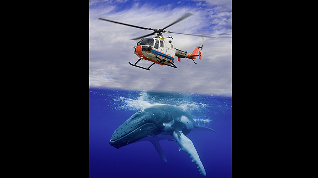 |
Photomontage of a humpback whale and the DLR helicopter Bo 105. Credit: DLR/istockphoto.com/Josh Friedmann |
Modern helicopters could be significantly faster and more manoeuvrable - if aerodynamics did not impose limitations on them. Researchers at the German Aerospace Center (Deutsches Zentrum für Luft- und Raumfahrt; DLR) in Göttingen have now discovered and flight-tested a way to increase manoeuvrability using an idea they got from observing humpback whales.
Unwanted turbulence
Helicopters owe their special ability to vertically take off and land to their main rotor, but this also contributes to aerodynamic disadvantages. The airflow over a backward-moving main rotor blade separating from the aerofoil during fast forward flight or manoeuvring, referred to as a 'dynamic stall', creates turbulence, loss of lift and exerts large forces on the rotor. Drag increases and the rotor head control rods are subjected to large dynamic loads. "This limits the top speed of helicopters at high altitude and, in particular, their manoeuvrability," explains Kai Richter from the DLR Institute of Aerodynamics and Flow Technology in Göttingen. In addition, the resulting vibration compromises passenger comfort. Modern engines would be able to deliver significantly better flight performance were it not for these limitations. "Stalling is one of the most serious problems in helicopter aerodynamics – and one of the most complex," says Richter. Generating a computer simulation of a moving rotor is significantly more complicated than modelling a fixed-wing aircraft.
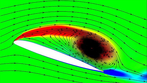 |
| A computer simulation shows turbulence around a rotor blade when the airflow separates from the aerofoil. This phenomenon, referred to as a 'dynamic stall', occurs on a backward-moving main rotor blade during fast forward flight or manoeuvring. Credit: DLR |
Acrobatic marine mammals
When looking for ways to delay the onset of stalling in helicopters, researchers at Göttingen struck gold with humpback whales - which is somewhat surprising at first glance. "These marine mammals are renowned for their great speed and acrobatic skills," says Holger Mai from the DLR Institute of Aeroelasticity. This is due to their unusually large pectoral fins, which have characteristic bumps along the front edge. "Research has shown that these bumps cause stalling to occur significantly later underwater and increase buoyancy."
DLR researchers translated the idea of using bumps for delaying the onset of stalling to helicopter rotors, and patented it as Leading-Edge Vortex Generators (LEVoGs) "Flow phenomena in water are similar to those in air; they just need to be scaled accordingly," says Mai. The artificial bumps on helicopters are smaller than those on a humpback whale; they have a diameter of six millimetres and weigh just 0.04 grams.
Experiments conducted in the wind tunnel were promising, enabling a test flight using the DLR Bo 105 research helicopter in Braunschweig to be successfully carried out, as part of the DLR SIMCOS (Advanced Simulation and Control of Dynamic Stall) project. 186 rubber LEVoGs were glued to each of the helicopter’s four rotor blades.
"The pilots have already noticed a difference in the behaviour of the rotor blades," says Richter. The main objective of the initial test flight was to demonstrate the safety of this new technique. "The next step is a flight using special measuring equipment to accurately record the effects," Richter explains.
If the concept proves successful, DLR researchers hope that existing helicopters could be retrofitted at little expense. For new helicopters, contours could be milled into the front edges of existing titanium blade designs during the manufacturing process.
Source: German Aerospace Center (DLR)
Robot reconnoiters uncharted terrain
Engineerblogger
Feb 1, 2012
Mobile robots have many uses. They serve as cleaners, carry out inspections and search for survivors of disasters. But often, there is no map to guide them through unknown territory. Researchers have now developed a mobile robot that can roam uncharted terrain and simultaneously map it – all thanks to an algorithm toolbox.
Industrial robots have been a familiar sight in the workplace for many years. In automotive and household appliance manufacture, for example, they have proved highly reliable on production and assembly lines. But now a new generation of high-tech helpers is at hand: Mobile robots are being used in place of humans to explore hazardous and difficult-to-access environments such as buildings in danger of collapsing, caves, or ground that has been polluted by an industrial accident. Equipped with sensors and optical cameras, these robots can help rescue services search for victims in the wake of natural disasters, explosions or fires, and can measure concentrations of hazardous substances. There’s just one problem: Often there is no map to show them the location of obstacles and steer them along navigable routes. Yet such maps are critical to ensuring that the high-tech machines are able to make progress, either independently or guided by remote control. Researchers at the Fraunhofer Institute for Optronics, System Technologies and Image Exploitation IOSB in Karlsruhe have now developed a roaming land robot that autonomously reconnoiters and maps uncharted terrain. The robot uses special algorithms and multi-sensor data to carve a path through unknown territory.
“To be able to navigate independently, our mobile robot has to fulfill a number of requirements. It must be able to localize itself within its immediate surroundings, continuously recalculate its position as it makes its way through the danger area, and simultaneously refine the map it is generating,” says graduate engineer Christian Frey of the IOSB. To make this possible, he and his team have developed an algorithm toolbox for the robot that runs on a built-in computer. The robot is additionally equipped with a variety of sensors. Odometry sensors measure wheel revolutions, inertial sensors compute accelerations, and distance-measuring sensors register clearance from walls, steps, trees and bushes, to name but a few potential obstacles. Cameras and laser scanners record the environment and assist in the mapping process. The algorithms read the various data supplied by the sensors and use them to determine the robot’s precise location. The interplay of all these different elements concurrently produces a map, which is updated continuously. Experts call the process Simultaneous Localization and Mapping, or SLAM.
Mobile robots face an additional challenge: to find the optimal path that will enable them to complete each individual task. Depending on the situation, this may be the shortest and quickest route, or perhaps the most energy-efficient, i.e. the one that uses the least amount of gasoline. When planning a course, the high-tech helpers must take into account restrictions on mobility such as a limited turning circle, and must navigate around obstacles. And should the environment change, for example as a result of falling objects or earthquake aftershocks, a robot must register this and use its toolbox to recalculate its route.
“We made our toolbox modular, so it’s not difficult to adapt the algorithms to suit different types of mobile robot or specific in- or outdoor application scenarios. For example, it doesn’t matter what sensor set-up is used, or whether the robot has two- or four-wheel drive,” says Frey. The software can be customized to meet the needs of individual users, with development work taking just a few months. Frey adds: “The toolbox is suitable for all sorts of situations, not only accident response scenarios. It can be installed in cleaning robots or lawnmowers, for example, and a further possible application would be in roaming robots used to patrol buildings or inspect gas pipelines for weak points.” From March 6-10, the IOSB researchers will be demonstrating their mobile robot technology at the CeBIT trade fair.
Source: Fraunhofer-Gesellschaft
Feb 1, 2012
 |
| Equipped with multiple sensors and optical cameras, the mobile robot roams over dangerous ground. © Fraunhofer IOSB |
Mobile robots have many uses. They serve as cleaners, carry out inspections and search for survivors of disasters. But often, there is no map to guide them through unknown territory. Researchers have now developed a mobile robot that can roam uncharted terrain and simultaneously map it – all thanks to an algorithm toolbox.
Industrial robots have been a familiar sight in the workplace for many years. In automotive and household appliance manufacture, for example, they have proved highly reliable on production and assembly lines. But now a new generation of high-tech helpers is at hand: Mobile robots are being used in place of humans to explore hazardous and difficult-to-access environments such as buildings in danger of collapsing, caves, or ground that has been polluted by an industrial accident. Equipped with sensors and optical cameras, these robots can help rescue services search for victims in the wake of natural disasters, explosions or fires, and can measure concentrations of hazardous substances. There’s just one problem: Often there is no map to show them the location of obstacles and steer them along navigable routes. Yet such maps are critical to ensuring that the high-tech machines are able to make progress, either independently or guided by remote control. Researchers at the Fraunhofer Institute for Optronics, System Technologies and Image Exploitation IOSB in Karlsruhe have now developed a roaming land robot that autonomously reconnoiters and maps uncharted terrain. The robot uses special algorithms and multi-sensor data to carve a path through unknown territory.
“To be able to navigate independently, our mobile robot has to fulfill a number of requirements. It must be able to localize itself within its immediate surroundings, continuously recalculate its position as it makes its way through the danger area, and simultaneously refine the map it is generating,” says graduate engineer Christian Frey of the IOSB. To make this possible, he and his team have developed an algorithm toolbox for the robot that runs on a built-in computer. The robot is additionally equipped with a variety of sensors. Odometry sensors measure wheel revolutions, inertial sensors compute accelerations, and distance-measuring sensors register clearance from walls, steps, trees and bushes, to name but a few potential obstacles. Cameras and laser scanners record the environment and assist in the mapping process. The algorithms read the various data supplied by the sensors and use them to determine the robot’s precise location. The interplay of all these different elements concurrently produces a map, which is updated continuously. Experts call the process Simultaneous Localization and Mapping, or SLAM.
Mobile robots face an additional challenge: to find the optimal path that will enable them to complete each individual task. Depending on the situation, this may be the shortest and quickest route, or perhaps the most energy-efficient, i.e. the one that uses the least amount of gasoline. When planning a course, the high-tech helpers must take into account restrictions on mobility such as a limited turning circle, and must navigate around obstacles. And should the environment change, for example as a result of falling objects or earthquake aftershocks, a robot must register this and use its toolbox to recalculate its route.
“We made our toolbox modular, so it’s not difficult to adapt the algorithms to suit different types of mobile robot or specific in- or outdoor application scenarios. For example, it doesn’t matter what sensor set-up is used, or whether the robot has two- or four-wheel drive,” says Frey. The software can be customized to meet the needs of individual users, with development work taking just a few months. Frey adds: “The toolbox is suitable for all sorts of situations, not only accident response scenarios. It can be installed in cleaning robots or lawnmowers, for example, and a further possible application would be in roaming robots used to patrol buildings or inspect gas pipelines for weak points.” From March 6-10, the IOSB researchers will be demonstrating their mobile robot technology at the CeBIT trade fair.
Source: Fraunhofer-Gesellschaft
Tuesday, January 31, 2012
New Ideas Sharpen Focus for Greener Aircraft
Engineerblogger
Jan 30, 2012
Leaner, greener flying machines for the year 2025 are on the drawing boards of three industry teams under contract to the NASA Aeronautics Research Mission Directorate's Environmentally Responsible Aviation Project.
Teams from The Boeing Company in Huntington Beach, Calif., Lockheed Martin in Palmdale, Calif., and Northrop Grumman in El Segundo, Calif., have spent the last year studying how to meet NASA goals to develop technology that would allow future aircraft to burn 50 percent less fuel than aircraft that entered service in 1998 (the baseline for the study), with 75 percent fewer harmful emissions; and to shrink the size of geographic areas affected by objectionable airport noise by 83 percent.
"The real challenge is we want to accomplish all these things simultaneously," said ERA project manager Fay Collier. "It's never been done before. We looked at some very difficult metrics and tried to push all those metrics down at the same time."
So NASA put that challenge to industry – awarding a little less than $11 million to the three teams to assess what kinds of aircraft designs and technologies could help meet the goals. The companies have just given NASA their results.
"We'll be digesting the three studies and we'll be looking into what to do next," said Collier.
Boeing's advanced vehicle concept centers around the company's now familiar blended wing body design as seen in the sub-scale remotely piloted X-48, which has been wind tunnel tested at NASA's Langley Research Center and flown at NASA's Dryden Flight Research Center. One thing that makes this concept different from current airplanes is the placement of its Pratt & Whitney geared turbofan engines. The engines are on top of the plane's back end, flanked by two vertical tails to shield people on the ground from engine noise. The aircraft also would feature an advanced lightweight, damage tolerant, composite structure; technologies for reducing airframe noise; advanced flight controls; hybrid laminar flow control, which means surfaces designed to reduce drag; and long-span wings which improve fuel efficiency.
Lockheed Martin took an entirely different approach. Its engineers proposed a box wing design, in which a front wing mounted on the lower belly of the plane is joined at the tips to an aft wing mounted on top of the plane. The company has studied the box wing concept for three decades, but has been waiting for lightweight composite materials, landing gear technologies, hybrid laminar flow and other tools to make it a viable configuration. Lockheed's proposal combines the unique design with a Rolls Royce Liberty Works Ultra Fan Engine. This engine has a bypass ratio that is approximately five times greater than current engines, pushing the limits of turbofan technology.
Northrop Grumman chose to embrace a little of its company's history, going back to the 1930s and '40s, with its advanced vehicle concept. Its design is a flying wing, championed by Northrop founder Jack Northrop, and reminiscent of its B-2 aircraft. Four high-bypass engines, provided by Rolls Royce and embedded in the upper surface of the aerodynamically efficient wing would provide noise shielding. The company's expertise in building planes without the benefit of a stabilizing tail would be transferred to the commercial airline market. The Northrop proposal also incorporates advanced composite materials and engine and swept wing laminar flow control technologies.
What the studies revealed is that NASA's goals to reduce fuel consumption, emissions and noise are indeed challenging. The preliminary designs all met the pollution goal of eliminating landing and takeoff emissions of nitrogen oxides by 50 percent. All still have a little way to go to meet the other two challenges. All the designs were very close to a 50-percent fuel burn reduction, but noise reduction capabilities varied.
"All of the teams have done really great work during this conceptual design study,” say Mark Mangelsdorf, ERA Project chief engineer. “Their results make me excited about how interesting and different the airplanes on the airport ramp could look in 20 years. Another great result of the study is that they have really helped us focus where to invest our research dollars over the next few years," he said.
NASA's ERA project officials say they believe all the goals can be met if small gains in noise and fuel consumption reduction can be achieved in addition to those projected in the industry studies. The results shed light on the technology and design hurdles airline manufacturers face in trying to design lean, green flying machines and will help guide NASA's environmentally responsible aviation investment strategy for the second half of its six-year project.
Source: NASA
Jan 30, 2012
 |
Three proposed aircraft designs have varying levels of success in meeting tough NASA goals for reducing fuel use, emissions and noise all at the same time. Image credit: NASA |
Leaner, greener flying machines for the year 2025 are on the drawing boards of three industry teams under contract to the NASA Aeronautics Research Mission Directorate's Environmentally Responsible Aviation Project.
Teams from The Boeing Company in Huntington Beach, Calif., Lockheed Martin in Palmdale, Calif., and Northrop Grumman in El Segundo, Calif., have spent the last year studying how to meet NASA goals to develop technology that would allow future aircraft to burn 50 percent less fuel than aircraft that entered service in 1998 (the baseline for the study), with 75 percent fewer harmful emissions; and to shrink the size of geographic areas affected by objectionable airport noise by 83 percent.
"The real challenge is we want to accomplish all these things simultaneously," said ERA project manager Fay Collier. "It's never been done before. We looked at some very difficult metrics and tried to push all those metrics down at the same time."
So NASA put that challenge to industry – awarding a little less than $11 million to the three teams to assess what kinds of aircraft designs and technologies could help meet the goals. The companies have just given NASA their results.
"We'll be digesting the three studies and we'll be looking into what to do next," said Collier.
Boeing's advanced vehicle concept centers around the company's now familiar blended wing body design as seen in the sub-scale remotely piloted X-48, which has been wind tunnel tested at NASA's Langley Research Center and flown at NASA's Dryden Flight Research Center. One thing that makes this concept different from current airplanes is the placement of its Pratt & Whitney geared turbofan engines. The engines are on top of the plane's back end, flanked by two vertical tails to shield people on the ground from engine noise. The aircraft also would feature an advanced lightweight, damage tolerant, composite structure; technologies for reducing airframe noise; advanced flight controls; hybrid laminar flow control, which means surfaces designed to reduce drag; and long-span wings which improve fuel efficiency.
 |
| The Boeing Company's advanced design concept is a variation on the extremely aerodynamic hybrid wing body. Image credit: NASA/Boeing |
Lockheed Martin took an entirely different approach. Its engineers proposed a box wing design, in which a front wing mounted on the lower belly of the plane is joined at the tips to an aft wing mounted on top of the plane. The company has studied the box wing concept for three decades, but has been waiting for lightweight composite materials, landing gear technologies, hybrid laminar flow and other tools to make it a viable configuration. Lockheed's proposal combines the unique design with a Rolls Royce Liberty Works Ultra Fan Engine. This engine has a bypass ratio that is approximately five times greater than current engines, pushing the limits of turbofan technology.
 |
| Lockheed Martin's concept uses a box wing design and other advanced technologies to achieve green aviation goals. Image credit: NASA/Lockheed Martin |
Northrop Grumman chose to embrace a little of its company's history, going back to the 1930s and '40s, with its advanced vehicle concept. Its design is a flying wing, championed by Northrop founder Jack Northrop, and reminiscent of its B-2 aircraft. Four high-bypass engines, provided by Rolls Royce and embedded in the upper surface of the aerodynamically efficient wing would provide noise shielding. The company's expertise in building planes without the benefit of a stabilizing tail would be transferred to the commercial airline market. The Northrop proposal also incorporates advanced composite materials and engine and swept wing laminar flow control technologies.
 |
| Northrop Grumman's concept is based on the extremely aerodynamic "flying wing" design. Image credit: NASA/Northrop Grumman |
What the studies revealed is that NASA's goals to reduce fuel consumption, emissions and noise are indeed challenging. The preliminary designs all met the pollution goal of eliminating landing and takeoff emissions of nitrogen oxides by 50 percent. All still have a little way to go to meet the other two challenges. All the designs were very close to a 50-percent fuel burn reduction, but noise reduction capabilities varied.
"All of the teams have done really great work during this conceptual design study,” say Mark Mangelsdorf, ERA Project chief engineer. “Their results make me excited about how interesting and different the airplanes on the airport ramp could look in 20 years. Another great result of the study is that they have really helped us focus where to invest our research dollars over the next few years," he said.
NASA's ERA project officials say they believe all the goals can be met if small gains in noise and fuel consumption reduction can be achieved in addition to those projected in the industry studies. The results shed light on the technology and design hurdles airline manufacturers face in trying to design lean, green flying machines and will help guide NASA's environmentally responsible aviation investment strategy for the second half of its six-year project.
Source: NASA
Scottish sailing engineers have designs on world speed record
The Engineer
Jan 23, 2012
Simulation software from Dassault is being used to help a team of engineers get its extreme sailing boat - the V-44 Albatross - off the ground
The thrilling world of speed-sailing is responsible for some remarkable engineering innovations.
Back in September 2009, L’Hydroptere, a 60ft trimaran that ’flies’ above the surface on two fin-shaped hydrofoils, set a new world record for D-class vessels of 51.36 knots.
More recently, The Engineer reported on the Vestas SailRocket II, a glider-inspired boat with designs on the outright unpowered 500m record of 55.65 knots.
Now, in a bid to push the performance of extreme sailing boats even further, a team of Scottish engineers is using advanced simulation software to design and develop a bizarre-looking vessel that the engineers believe could soon break the near-mythical 60-knot barrier.
The boat, dubbed the V-44 Albatross, is the brainchild of Tim Clarke, engineering team leader at Scottish engineering consultancy Prospect Flow Solutions and founder of Verney Yachts.
Clarke explained that his idea was to create a single-hull craft and equip it with two wing-sails – structures that are literally a cross between a wing and a sail.
Made from composite materials, these wing-sails are able to switch both position and function as the boat tacks, becoming either a wing if horizontal to the water or a sail if vertical.
The approach has been tried before. The BMW Oracle, a trimaran sailboat, crushed its America’s Cup competitor in February 2010 using a wing-sail, while the Greenbird, a wing-sail-equipped land-yacht, set a new wind-powered land speed record of 126.4mph back in March 2009.
One of the challenges of developing a wing-sail is ensuring stability. While a conventional aircraft wing needs a tail to provide stability, this would add too much weight to a boat so wing-sail vessels typically achieve stability in other ways. For the BMW Oracle, a motorised trailing flap on a two-part structure was used, while the Greenbird deployed counterweights on the leading edge.
Jan 23, 2012
 |
The Abaqus software enabled Clarke’s team to consider many wing-sail design variables. Credit: The Engineer |
Simulation software from Dassault is being used to help a team of engineers get its extreme sailing boat - the V-44 Albatross - off the ground
The thrilling world of speed-sailing is responsible for some remarkable engineering innovations.
Back in September 2009, L’Hydroptere, a 60ft trimaran that ’flies’ above the surface on two fin-shaped hydrofoils, set a new world record for D-class vessels of 51.36 knots.
More recently, The Engineer reported on the Vestas SailRocket II, a glider-inspired boat with designs on the outright unpowered 500m record of 55.65 knots.
Now, in a bid to push the performance of extreme sailing boats even further, a team of Scottish engineers is using advanced simulation software to design and develop a bizarre-looking vessel that the engineers believe could soon break the near-mythical 60-knot barrier.
The boat, dubbed the V-44 Albatross, is the brainchild of Tim Clarke, engineering team leader at Scottish engineering consultancy Prospect Flow Solutions and founder of Verney Yachts.
Clarke explained that his idea was to create a single-hull craft and equip it with two wing-sails – structures that are literally a cross between a wing and a sail.
Made from composite materials, these wing-sails are able to switch both position and function as the boat tacks, becoming either a wing if horizontal to the water or a sail if vertical.
The approach has been tried before. The BMW Oracle, a trimaran sailboat, crushed its America’s Cup competitor in February 2010 using a wing-sail, while the Greenbird, a wing-sail-equipped land-yacht, set a new wind-powered land speed record of 126.4mph back in March 2009.
One of the challenges of developing a wing-sail is ensuring stability. While a conventional aircraft wing needs a tail to provide stability, this would add too much weight to a boat so wing-sail vessels typically achieve stability in other ways. For the BMW Oracle, a motorised trailing flap on a two-part structure was used, while the Greenbird deployed counterweights on the leading edge.
Monday, January 30, 2012
New Capabilities of today’s Automotive Glass Equipment
Engineerblogger
Jan 30, 2012
Today’s know-how, together with new developments in control technology and machine production technologies allow to utilise automotive glass grinding and cutting machines in new ways.
This equipment with its more flexible use, can reach higher quality and/or much shorter cycle times as well as it is open for new applications.
New equipment with direct drive technology is able to preprocess glass in a higher quality and at the same time faster than in the past. Thanks to the drives the gearboxes can be eliminated, higher torque can be achieved and higher resolution encoders can be used. Eliminating the gearboxes menas eliminating the mechanical play totally. The accuracy is given by the measurement system and the performance of the drive regulator. The measurement systems can resolve down to micrometers or micronarcs for polar systems.
Using the new technology the customers do not have to decide between productivity and quality to a given price. The new controls allow to adapt the production quality to the desired level. For example a customer can start its venture in the less demanding replacement segment, where high output is critical. If he is looking for new opportunities later it is possible to reprogram the machine to the highest quality levels. The customer is able to compete on the highest quality levels which allow asking for a higher price for the manufactured product. Todays new electronic developments allow an easy and riskless adaption of parameters. The technology, accuracy and flexibility can be applied in other glass production fields like solar or architectural production as well.
Technical basis of champ’speed
Working with two cutting bridges allows to separate relief cuts and form cuts. Furthermore the customer can separate cutting and breaking if needed. Using the correct combination distributing the processes allows moving the bottleneck process in cutting and grinding from the cutting/breaking into the grinding operation. The best combination depends on the design of the end product. In most of the cases the best solution is to do the relieve cuts on the first station and the cutting and breaking on the second station. Having two independent cutting heads with one breaking ball head gives room for the very best possible combination to increase the quality and accuracy to the maximum with the lowest possible cycle time.
Producing a form with an accuracy of 100 percent is possible but physical parameters limit the cycle time. If needed, the machine can follow the contour exactly. This will result in a very accurate glass, but takes its time. In theory, the relation between grinding speed and forward movement should be constant. To reach a constant grinding surface the speed has to be reduced at each point where the grinding spindle makes a turn or goes around an edge. This means: the smaller the radius, the lower the speed. As the grinding wheel has a diameter, the speed of its centre point has to increase, because it has to travel a much longer way than the grinding point of the glass. In an inner arc, the travelling speed has to be reduced, because otherwise the wheel would take too much glass and will get choked.
Today there are two ways, to achieve high speed and accuracy. Firstly it is possible to make the design of the form in a way that the end result will still be in specs. This means that the design is not in the middle of the tolerance field designed, but will touch the limits with working in lower tolerance bands. The achieved result is still the same (faster production cycle, in given tolerance), but the result does not depend on factors like speed or grinding wheel diameters anymore. Secondly one can do the same like in the past i.e. opening the contour error and allow bigger deviation. But with these methods the resulting form will then depend again on process parameters like speed. This method is not recommended but is very easy to do and does not require additional know-how or skill, but the production cycle improvement can still be considerable.
Additional to the improvement in cycle time due to the higher moment of the motor, a well designed grinding path can add considerable cycle time advantages. Together with using two bridge cutting and direct drive grinders, the cycle time can come from 27 seconds for a windshield down to 16 seconds, for the same design.
Higher torque and higher accuracy allow on polar machine to increase the diameter range. Not only windshields for trucks and busses but also solar glasses or other high end glass with diagonals up to 3.6m are possible to grind with accuracies below 0.1mm around the whole circumference. This accuracy can be achieved with low cost process due to low cycle times, automotive approved equipment and low cost consumables.
Commercial applications
The investment is not much different than in the past, but the cycle times improve a lot on the same production space. This alone can justify a replacement of machines. Higher torque motors allow running the grinders faster and more accurate. Adding the possibility to use the tolerance band in improving cycle time gives more flexibility. The decision to invest in accurate or fast equipment has not to be taken anymore. The equipment can be bought and during the time of use switched by parameters to either use the machine in a mode with very low tolerances or in a mode with very high precision.
A company can start of in producing replacement glass with very high output and low cost for example and switch for other projects to OEM manufacturing parameters with high machine and process capabilities and insuring six sigma tolerances or more. The characteristic of the equipment can cater for different markets and customers by simply pushing a button or by an intelligent design. Using this way also small companies can invest and be sure, that the equipment keeps its value for all future ventures and supports future expansions. For solar glass new dimensions of accuracy can be achieved by low costs. The flexibility is there to adjust in the future to all needs of forms or accuracy. Proven process capabilities are given out of the automotive industry.
With this equipment producing changing models is possible without making test glasses. It is possible to change from one model to the next, without wasting one glass and without tweaking parameters. Change over time is dramatically reduced and lower skilled personal can handle the machines.
Conclusion – Limitations and things to consider
Due to the fact, that the machine does what the program defines, it means that a form has to be defined 100% correctly. The machine follows the drawing exactly. The CAD-drawing must include all detail and the transition from one drawing element to the next. Transitions of elements have to be correct and tangents have to be handled with care and accuracy. This higher demand in designing capabilities might allow to reduce the capabilities of the machine operator.
About Bystronic Glass
Bystronic glass is the most competent and reliable partner for services, machinery, plants and systems in the glass processing sector. Bystronic glass supplies its well-proven machine technologies also in important areas of the photovoltaic industry. This includes preprocessing, front-end and back-end solutions. Bystronic glass is an international brand with globally operating companies that support their customers on site and through own sales and service companies. Since 1994, Bystronic glass is part of the Conzzeta AG, a renowned Swiss industrial holding company.
Source: Glass on Web
Additional Information:
Jan 30, 2012
Today’s know-how, together with new developments in control technology and machine production technologies allow to utilise automotive glass grinding and cutting machines in new ways.
This equipment with its more flexible use, can reach higher quality and/or much shorter cycle times as well as it is open for new applications.
New equipment with direct drive technology is able to preprocess glass in a higher quality and at the same time faster than in the past. Thanks to the drives the gearboxes can be eliminated, higher torque can be achieved and higher resolution encoders can be used. Eliminating the gearboxes menas eliminating the mechanical play totally. The accuracy is given by the measurement system and the performance of the drive regulator. The measurement systems can resolve down to micrometers or micronarcs for polar systems.
Using the new technology the customers do not have to decide between productivity and quality to a given price. The new controls allow to adapt the production quality to the desired level. For example a customer can start its venture in the less demanding replacement segment, where high output is critical. If he is looking for new opportunities later it is possible to reprogram the machine to the highest quality levels. The customer is able to compete on the highest quality levels which allow asking for a higher price for the manufactured product. Todays new electronic developments allow an easy and riskless adaption of parameters. The technology, accuracy and flexibility can be applied in other glass production fields like solar or architectural production as well.
Technical basis of champ’speed
Working with two cutting bridges allows to separate relief cuts and form cuts. Furthermore the customer can separate cutting and breaking if needed. Using the correct combination distributing the processes allows moving the bottleneck process in cutting and grinding from the cutting/breaking into the grinding operation. The best combination depends on the design of the end product. In most of the cases the best solution is to do the relieve cuts on the first station and the cutting and breaking on the second station. Having two independent cutting heads with one breaking ball head gives room for the very best possible combination to increase the quality and accuracy to the maximum with the lowest possible cycle time.
 |
| Figure 1: Example windscreen |
Producing a form with an accuracy of 100 percent is possible but physical parameters limit the cycle time. If needed, the machine can follow the contour exactly. This will result in a very accurate glass, but takes its time. In theory, the relation between grinding speed and forward movement should be constant. To reach a constant grinding surface the speed has to be reduced at each point where the grinding spindle makes a turn or goes around an edge. This means: the smaller the radius, the lower the speed. As the grinding wheel has a diameter, the speed of its centre point has to increase, because it has to travel a much longer way than the grinding point of the glass. In an inner arc, the travelling speed has to be reduced, because otherwise the wheel would take too much glass and will get choked.
Today there are two ways, to achieve high speed and accuracy. Firstly it is possible to make the design of the form in a way that the end result will still be in specs. This means that the design is not in the middle of the tolerance field designed, but will touch the limits with working in lower tolerance bands. The achieved result is still the same (faster production cycle, in given tolerance), but the result does not depend on factors like speed or grinding wheel diameters anymore. Secondly one can do the same like in the past i.e. opening the contour error and allow bigger deviation. But with these methods the resulting form will then depend again on process parameters like speed. This method is not recommended but is very easy to do and does not require additional know-how or skill, but the production cycle improvement can still be considerable.
 |
| Figure 2: Cutting path with new equipment can increase corner speeds, improve quality and is reproducible |
Additional to the improvement in cycle time due to the higher moment of the motor, a well designed grinding path can add considerable cycle time advantages. Together with using two bridge cutting and direct drive grinders, the cycle time can come from 27 seconds for a windshield down to 16 seconds, for the same design.
Higher torque and higher accuracy allow on polar machine to increase the diameter range. Not only windshields for trucks and busses but also solar glasses or other high end glass with diagonals up to 3.6m are possible to grind with accuracies below 0.1mm around the whole circumference. This accuracy can be achieved with low cost process due to low cycle times, automotive approved equipment and low cost consumables.
 |
| Figure 3: Trajectory speed of the grinding wheel center |
Commercial applications
The investment is not much different than in the past, but the cycle times improve a lot on the same production space. This alone can justify a replacement of machines. Higher torque motors allow running the grinders faster and more accurate. Adding the possibility to use the tolerance band in improving cycle time gives more flexibility. The decision to invest in accurate or fast equipment has not to be taken anymore. The equipment can be bought and during the time of use switched by parameters to either use the machine in a mode with very low tolerances or in a mode with very high precision.
A company can start of in producing replacement glass with very high output and low cost for example and switch for other projects to OEM manufacturing parameters with high machine and process capabilities and insuring six sigma tolerances or more. The characteristic of the equipment can cater for different markets and customers by simply pushing a button or by an intelligent design. Using this way also small companies can invest and be sure, that the equipment keeps its value for all future ventures and supports future expansions. For solar glass new dimensions of accuracy can be achieved by low costs. The flexibility is there to adjust in the future to all needs of forms or accuracy. Proven process capabilities are given out of the automotive industry.
With this equipment producing changing models is possible without making test glasses. It is possible to change from one model to the next, without wasting one glass and without tweaking parameters. Change over time is dramatically reduced and lower skilled personal can handle the machines.
 |
| Figure 4: Example of a new automotive glass preprocessing equipment – champ’speed-line of Bystronic glass |
Conclusion – Limitations and things to consider
Due to the fact, that the machine does what the program defines, it means that a form has to be defined 100% correctly. The machine follows the drawing exactly. The CAD-drawing must include all detail and the transition from one drawing element to the next. Transitions of elements have to be correct and tangents have to be handled with care and accuracy. This higher demand in designing capabilities might allow to reduce the capabilities of the machine operator.
About Bystronic Glass
Bystronic glass is the most competent and reliable partner for services, machinery, plants and systems in the glass processing sector. Bystronic glass supplies its well-proven machine technologies also in important areas of the photovoltaic industry. This includes preprocessing, front-end and back-end solutions. Bystronic glass is an international brand with globally operating companies that support their customers on site and through own sales and service companies. Since 1994, Bystronic glass is part of the Conzzeta AG, a renowned Swiss industrial holding company.
Source: Glass on Web
Additional Information:
Subscribe to:
Posts (Atom)


